
In this set of articles, I’m going to be looking at mains powered linear power supplies (PSU’s) but before we start, a word of caution.
You should already be aware that the domestic mains voltage, which ranges anywhere from around 110v to 250v AC depending on your country, is lethal and will kill you if you don’t show it proper respect. Please, if you’re uncomfortable with the idea of working with mains voltage don’t take the chance.
Just remember, there’s no substitute for common sense and being careful.
For safety help and information, please read part 1.
The oscilloscope display
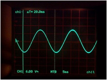
The image on the left shows a 50Hz sine wave. The image is being shown on a piece of test equipment called an oscilloscope, and this instrument allows us to see a visual representation of what’s happening in a circuit.
At the bottom of the display it states the signal that is being displayed is from Channel 1. Each square represents a voltage of 6v, so the the highest part of the wave form, to the lowest part of the wave form is approximately 3 squares, so 3 x 6 = 18v peak-to-peak.
You can ignore the MTB, but the 5ms is important. This is the sweep frequency of the oscilloscope and states that each square is 5ms wide.
At the top of the display is a value; 20ms in this case which is displaying the period between the two vertical lines on the display. The vertical lines in this image are four squares apart, and as the MTB is set to 5ms that equates to 20ms (5ms x 4 squares = 20ms).
In the UK and many other countries, the mains voltage is around 230 volts AC at a frequency 50Hz.
If you look carefully at the left hand side and half way up, you will see a little mark, “1-“. This is the Zero point for channel 1 and is important to know where this point is.
Following the trace display starting at the far left, you will see that it curves down below the level of the Zero point, then swings back up, crosses the Zero point and rises to a peek and then curves back down to repeat the cycle.
This indicates that the voltage first goes negative; in reference to the zero point, and then positive in reference to the zero point; The signal is “alternating” between negative and positive hence it’s called AC; Alternating Current. You can see that from the zero point to the upper peek of the signal is about one and a half squares; this equates to around 9 volts.
Since the trace goes up one and a half squares above the zero point (so 9v) and then swings down below the zero point also one and a half squares, this indicates a voltage of -9v.
It’s also possible to use the display to calculate the frequency of the waveform that’s being displayed.
The display tells us that the waveform “period”; a complete cycle of the waveform which is from any point along the trace to the next identical point on the trace, is 20ms
To convert the period to frequency is simple with the following formula:
1 / 20ms = 0.05 = 50 Hz
We now know that the wave form is showing us a 9v peak-to-peak (9v above the zero line, and 9v below the zero line) at 50 Hz.
The secondary winding
The secondary winding(s) of a transformer is where we get our useable power from.
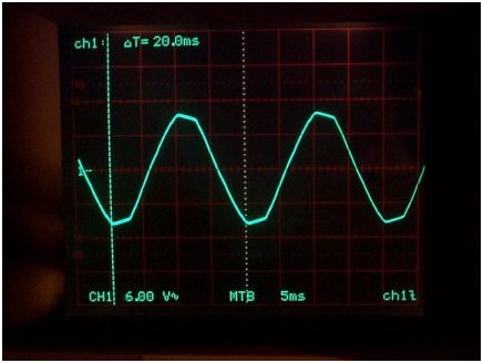
The trace on the left was taken directly off the secondary winding of a 6v transformer; the transformer isn’t connected to anything other than the mains supply and the scope’s input.
So if the scope is set to display 6 volts per square, and it’s a 6v transformer, why is the signal peeking at around one and a half squares above and below the centre line; that’s around 9v? Come to think about it, isn’t AC supposed to be a pure sine wave like the one being displayed in above image?
Whilst the trace on the left looks like a sine wave, there is a slight flattening or clipping at the top and bottom of the waveform peeks.
Clipped sine wave output
Firstly, the AC supply isn’t perfect; it has a Thevenin equivalent series resistance greater than zero ohms (go check Wiki if you’re interested).
Then there are long power cable runs, distribution transformers and substations along the way, each introducing additional resistance and imperfections. Finally there is your transformer which isn’t perfect either. All these factors add to distort the sine wave.
Transformer output voltage
The transformer in question does have a 6 volt secondary and its details are even printed on the side, but the scope display clearly shows that the output voltage is much higher than that specified.
Remember that the secondary winding (which is a huge long piece of wire) has resistance so that as the current draw increases, the voltage will start to drop, so manufacturers design transformers to output a nominal voltage when under load. Because the transformer being used to generate the trace above is not being loaded, the secondary voltage is higher than expected and you need to sometimes be mindful of this.
You must also consider that the transformer output voltage is directly related to the input voltage on the transformers primary side, and any input fluctuations will have knock on affects to the output.
Lets assume that our mains supply voltage is 240v, and using the transformer above, the secondary output voltage is 6v.
240v / 6v = 40 so for every 40 volts on the primary winding, we get 1 volt on the secondary; the transformer is said to have a 40:1 ratio.
Now we know the ratio, we can calculate what happens if the mains voltage should drop to say 225 volts.
225v / 40 = 5.625 volts.
Or, what happens if the mains voltage should rise to say 250v
250v / 40 = 6.25 volts.
So a slight variation of mains voltage on the transformer primary affects the output voltage on the secondary.
Transformer VA ratings again
In part 1 I briefly mentioned how to use the VA rating of the transformer to calculate the maximum current that it can supply from its secondary.
To recap:
Transformer VA rating / secondary voltage = available current
I also stated that transformers can have multiple secondary windings and that these windings don’t have to be of the same voltage; and they don’t.
Back in the days when TV’s had CRT’s and were full of valves (tubes), many different voltages were needed to run everything. Typically a low voltage; perhaps 6.3v was required for the valve/tube heaters, then a higher voltage for the electronics and then a really high voltage to generate the HT for the CRT.
But a VA rating won’t really help you much if you’ve got multiple secondary’s all of different voltages.
I’ve tried to think back to the last time I remember using a transformer with multiple secondary voltages and the last one I can remember was in an oscilloscope that I built when I was a lad, and a quick look through my favourite electronics suppliers catalogue confirmed what I’d started to suspect; nobody seems to be generally supplying transformers with multiple secondary windings of different voltages. Multiple secondary windings are very common indeed but they are usually for the same voltage and current rating.
What you need to remember is that the available current result from the VA calculation, is split across all secondary windings. A 50 VA transformer has a total of 50 VA, it’s not 50 VA per secondary winding.
Basic transformer configurations
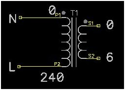
This is about the simplest transformer you will find.
It has a single secondary winding so all available voltage and current is available from the one secondary winding via connections S1 & S2.
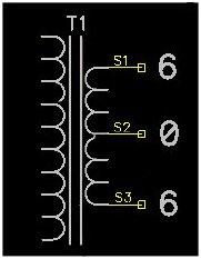
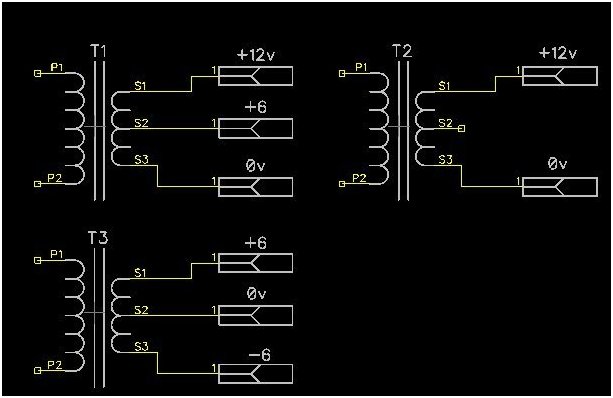
You have several options when using a centre-tap transformer in a design. The transformer shown has a single winding but has a tap from the centre of the winding and this makes the transformer very useful in some applications.
Whilst the term “centre-tap” is common enough, the “tap” doesn’t actually have to be in the centre and this was common in older transformers. For example, in the above transformer the centre tap could actually be moved 25% of the way down the winding instead of 50%, this would allow for different output voltage combinations. These days it’s more common for the tap to be in the centre of the winding as this gives symmetrical voltage outputs (+6 and -6 in our example) and this are rather useful when creating power supply units for driving operational or audio power amplifiers.
Dual secondary windings
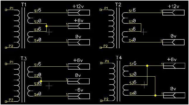
As common as the centre tapped transformer configuration is the transformer with dual secondary windings. These transformers seem to becoming the norm these days, possibly because for no real additional labour or material costs, you get additional benefits over other designs.
The previous centre tapped configurations for T1, T2 & T3 are identical to the T1, T2 & T3 configurations for a transformer with a dual secondary windings.
The big difference is the configuration used for T4.
Here the two windings are connected in parallel. Whilst this keeps the voltage output the same, it doubles the available current; this is something that’s not really possible with a centre-tapped secondary.
A word of caution. You MUST make sure that when connecting secondary windings together to combine their current capabilities, they are of the same voltage, and connected in phase (see how the 0 pins are connected together and then the 6v pins are connected together) for T4. If you get the phase wrong the transformer will burn itself out, quite spectacularly sometimes and remarkably quickly.
Leave a Reply
You must be logged in to post a comment.