
Safety and transformer basics
In this set of articles, I’m going to be looking at mains powered linear power supplies (PSU’s) but before we start, a word of caution.
You should already be aware that the domestic mains voltage, which ranges anywhere from around 90v to 250v or more depending on your country, is lethal and will kill you if you don’t show it proper respect. Please, if you’re uncomfortable with the idea of working with mains voltage don’t take the chance.
One hand in your pocket
TV engineers used to say that when working on live equipment, you should always work with one hand in your pocket. When you’re poking around inside a cramp, live TV chassis, trying to trace a circuit or get a meter probe to the right spot, it’s hard to keep track of exactly where one hand is, but keeping track of both of them is almost impossible.
Whilst this isn’t a technique that I’ve personally used as I’m too young to have needed to work on old valve (tube) TV’s that often had a live chassis, I can certainly appreciate the motivation behind it. Even if you have plenty of room to move and see what’s going on, it’s difficult to keep track of both hands sometimes. Be carful !!
If it’s metal it should be earthed… shouldn’t it?
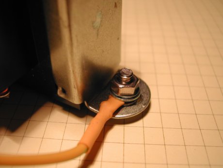
If the transformer has a metal chassis, don’t be tempted to skimp on an Earth connection. Attach the earth lead to a solder or crimp tag and bolt it to one of the transformer’s metal mounting points.
Do this even if the final mounting position for the transformer is within a non-conductive project box.
If your project housing is going to be metal, you must have an earth connection.
However, during project build or repair an earth may actually be more of a hindrance than an asset.
The big risk when working on live equipment is that you come into contact with a part of the circuit that is live; also called “Hot”, and the current travels through you to earth and as a result, you get an electric shock. Unfortunately, most of the metal electrical items around you; everything from the table lamp to soldering iron are also probably earthed; so there are many opportunities for you to complete the circuit path. If you’re being careful, you’re less likely to touch both the live and the neutral at the same time so I personally believe that you’re most likely to get a live to earth shock.
But why do you get a shock when you touch only the live?
The reason for this is that the power company connects the neutral to earth. How this is actually done depends on local regulations, but at some point in the cabling to your house, they connect the neutral and earth together. The earth connection is typically just that; a metal rod (usually brass), sunk several feet into the ground. This means that when you touch the live, current flows through your body and to earth and because of the earth / neutral bonding, you complete the circuit and get a shock.
Until you look a little deeper into how this works, it may seem a rather silly way of doing things. I mean, having the neutral connected to the earth makes it much more likely that you’re going to get electrocuted doesn’t it?
Well, it would if it weren’t for a device called the RCD.
The RCD (Residual Current Device) is your friend
The RCD, ELCB (Earth Leakage Circuit Breaker) or RCCD (Residual Current Circuit Device) units are designed to detect current leakage from Live to Earth, and to disconnect the power or “Trip” if this leakage exceeds a pre-defined value; usually around 30ma in a domestic fuse box. They are not designed to detect over current situations unless they are enhanced specifically for that purpose and because of this, they may not detect a live to neutral short circuit. They work on the principle that in a circuit, any current entering the device on the live connection, must leave on the neutral connection, and any imbalance between the two values means that current is leaking off to earth indicating a fault condition.
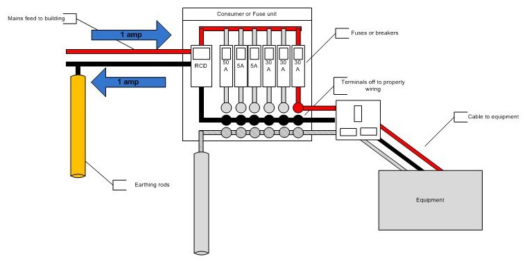
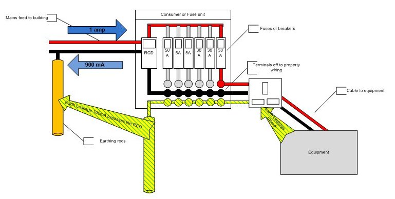
Figure 3 shows a small leakage of current from live to earth within the equipment. This leakage current travels down the earth and returns back to the power company bypassing the RCD in the consumer unit; the current has to return to complete the circuit, and this generates an imbalance in the RCD which causes it to trip, cutting off the power.
As well as large RCD’s designed to protect entire power installations or properties, you will often find smaller RCD’s plugged into mains sockets that are being using to power electric lawn mowers or any other outdoor mains powered equipment.
So, the RCD can only help protect against Live-Earth faults; these are faults where the current flows from the live through to an earth point. One possible cause is if YOU accidentally form a circuit path between a live point and earth when poking around inside a piece of equipment; your hand or arm is resting against a metal earthed chassis and you accidentally touch something live.
An RCD will not protect you from Live to Neutral faults; that’s where your body completes the circuit between Live and Neutral unless some of the current; more than 30ma typically; can pass through you to Earth.
Notice I say “only help protect”… as that’s all it will do. You may still get a shock as it can take tens of milliseconds for the RCD to detect the leakage and trip and I’m not sure I would bet my life on one of these cheap imported and mass produced devices saving my life, but you stand a much better chance of walking away from it if there’s an RCD fitted.
The RCD should be tested every couple of months using the Test button located on the it’s front. These devices are fairly cheap to purchase and it’s foolish not to have one kicking around the workshop if you are playing with the insides of mains powered equipment; either building, testing or repairing.
Most modern houses are fitted with an RCD in the main consumer unit, but since my life may depend on it, I tend to have a separate one on the bench for protecting individual items of equipment that I’m working on.
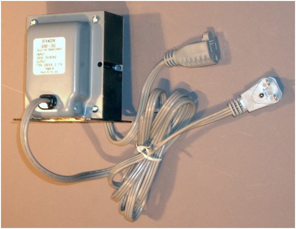
There are some additional notes and suggestions on safety at the end of this article but for now, let’s start to take a first look at transformers.
I’m not going to cover transformer theory and design in this article as it’s an entire subject in its own right, and there are plenty of resources available that explain all this in excruciating detail, but we do need to look at some of the basics and cover some of the terminology.
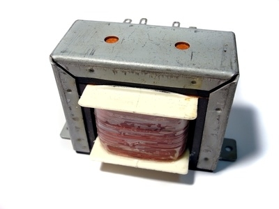
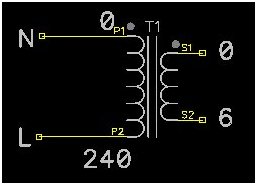
Voltage Transformers are used to convert one AC voltage to another. The input voltage is applied to the Primary side winding of the transformer, and the output voltage is taken from the Secondary side winding.
Voltage transformers only work with AC. They expect an AC voltage in, and they provide an AC voltage out.
It’s more common for the primary voltage to be higher than the secondary voltage; this is a step-down transformer, but it doesn’t have to work this way. TV sets and Oscilloscopes with CRT’s (Cathode Ray Tubes) often have a transformer that has a secondary winding to provide the HT (High Tension) voltage that can be several times higher than the primary side voltage; this is a step-up transformer. Just to confuse things slightly, it used to be quite common to see transformers that had both step-up and step-down secondaries on the same transformer; a HT secondary to drive the CRT, a 6.3v secondary to drive the heaters for the valves/tubes and CRT, some other voltages to drive the electronics.
Transformers can have single or multiple combinations of primary and secondary windings to enable them to work from, and produce many different voltages. There is a limitless number of types and configurations of Voltage Transformer available; however, they all basically work in the same way.
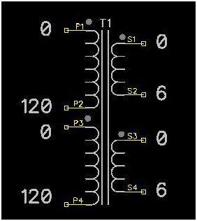
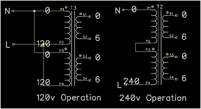
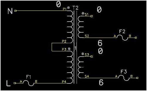
Certainly in Europe, the middle transformer image above irrespective of the number of secondary windings, is probably the most common. It has two primary windings, each rated at 120v. This means that the transformer can be used in countries with mains supplies of either 120v or 240v and the right hand image shows how the same transformer can be configured for either 120v or 240v operation.
For 120v operation, the transformer has its two Primary windings wired in parallel. It’s imperative that when connecting windings in parallel, they are connected in phase. Actually, this is more of an issue when dealing with secondary windings, but you should try and get into the habit of being aware of phases of the windings when connecting them in parallel.
The 0 & 0 of each winding are connected together (start of the windings), and the 120 and 120 are also connected together (end of the windings). You will also see that the symbols for the transformer have little “dots” located at one end of the winding and these indicate the start of the winding.
If the transformer above was used for 120v but only one Primary winding was used, only half the transformers rated current would be available from the transformers secondary; trying to draw more would overload the used primary winding, so it’s important to use both the windings.
If the transformer is wired for 240v operation but was actually run at 120v, then the secondary voltage would be half what is expected.
It should go without saying that if the transformer was configured for 120v but then run at 240v there would be a rather large cloud of smoke and probably a fire.
Multi-tap primary transformers
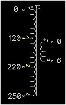
Before SMPS (Switch Mode Power Supplies) became common place, equipment that had to operate from multiple input voltages had a large primary winding rated for the maximum main input voltage expected, and then had “taps” off the winding to allow a range of smaller input voltages to be supplied.
You would often see these “taps” connected to a voltage selector plug at the rear of the equipment and the importer of the equipment would usually make sure that the voltage selector was set correctly for their country.
Additional properties of transformers.
An isolation transformer is basically a voltage transformer with a few differences. The Primary and Secondary windings are wound identically, so the output voltage is equal to the input voltage; the transformer has a ratio of 1:1, and additional precautions are taken to make sure that any capacitive coupling between the two windings is kept to the absolute minimum.
Because there is isolation between the two windings, loads on the secondary side of the transformer are isolated from the mains supply on the primary side and thus the equipment is isolated from any earth / neutral bonding on the primary side. The upshot of this is that if you plug a piece of equipment into an isolation transformer, and then accidentally touch something live within the equipment and also touch the earthed metal desk lamp next to you, or more likely, touch the negative on your oscilloscope probe, it’s impossible for the circuit to earth to be completed and you shouldn’t get a shock.
Isolation transformers tend to be quite expensive as it requires extra design and build effort to eliminate the capacitive coupling affects that can exist between the primary and secondary windings and to the transformer metal work, but it is possible to construct an isolation transformer from two separate but identical transformers. We shall look at building an isolation transformer equivalent later on.
More on safety – Fuses
Mistakes and faults are going to happen; the trick is to still be alive afterwards and a nice to have is for the equipment to survive as well.
In the UK at least, all 3-pin mains plugs have a mandatory fuse fitted. These fuses are great but you need to make sure they are correctly rated for the task. UK mains fuses are usually supplied in 3 / 5 / 10 or 13 amp ratings (unfortunately the default fuse fitted to a plug is usually 13 amps) but even the 3 amp fuse can be too high a rating for some projects. Fit the lowest value fuse you can for your project, but also fit a fuse closer to the transformers primary. You will often see this fuse located on the back of equipment near where the mains power connector is; sometimes it’s actually built into the actual mains connector or power switch. Some manufacturers prefer to place the fuse inside the equipment and locate it very close to the transformer.
No matter where this fuse is located, it allows the manufacturer to specify a fuse and type that is a better fit for the application, and also caters for countries that don’t have provision for fuses in their mains plugs.
Fuse types
Fuses come in many different styles, types and sizes. Style and size are really down to local availability and personal preference, but the “type” of fuse to use and its rating requires a little thought.
It should be mentioned that some transformers are fitted with an internal, single-shot, thermal fuse. If the transformer gets too hot, the fuse will blow and the transformer is then useless. Under normal conditions, the internal fuse cannot be reset or replaced.
When a transformer is first powered on, there is an inrush of current; this refers to the maximum instantaneous current drawn by the transformer when it’s powered on and this “spike” which can last for several mains cycles can be well above the maximum rating of the transformer; Toroidal transformers are even worse for this, and this large inrush current can make calculating fuses amperages difficult.
Fortunately fuses take time to generate enough heat to melt the fuse wire and blow, and this blow time is usually longer than it takes for the inrush event to be over. However, the fuse can be weakened during this inrush time and this is one of the reasons why fuses sometimes randomly blow even though there is no fault with the equipment.
Before we can look at calculating fuse ratings, we need to understand about transformer ratings.
Transformer VA ratings
When I was a lad, transformers used to have a label stamped on them that said 6v at 2amps and it was plain as day that the transformer had a 6v secondary winding rated at 2 amps. These days, transformers have a VA rating but fortunately the maths involved to makes sense of this VA rating is nice and simple.
Let’s assume we have in our hands a 50VA transformer. It has a 240v primary winding, and a 6v secondary winding (according to the label).
The current drawn by the primary winding can be calculated like this:
50 VA / 240v = 0.208 amps
The current capability of the secondary winding can be calculated like this:
50 VA / 6V = 8.3 amps
So when the transformer’s secondary is fully loaded, the primary winding will be drawing just over 200mA.
The VA rating of transformers does make it simpler in my opinion to work out the currents being drawn and available on the different windings.
For maximum protection, a transformer should be fitted with at least two fuses; one for the primary and one for the secondary. The primary fuse is really here to try and eliminate any fire risk caused with faults in the primary winding or other wiring faults around the primary connections. A transformer can suffer from shorted turns; this is where the enamel coating on the wire of the winding in the transformer is damaged and some of the turns short out. These shorts slightly change the voltage rating of the transformer and can cause it to run hotter, which can in turn melt more of the enamel, leading to more shorted turns and the process starts to run away out of control until the transformer burns out; possibly bursting into flames in the process. As the turns short out, the primary winding draws more and more current hopefully blowing the fuse before too much heat is generated and possibly preventing a fire.
The fuse on the secondary won’t protect against shorted turns, but it will protect the transformer from short circuits; a common cause of a short circuit is a rectifier or voltage regulator failing, or a wiring mistake. Using a fuse rated as close to the secondary current rating but certainly not exceeding it should be fitted; this fuse should be a fast blow type.
Note that the transformer in figure 8 has multiple secondary windings and in this configuration, both secondary windings should be protected, but we will look more at the secondary side of things later on.
When calculating the fuse for the primary side of the transformer, we have to remember to take into account the inrush current; inrush doesn’t apply to the secondary.
Transformer inrush current
When a transformer is first energised, a transient current up to 50 times larger than the rated transformer current can flow and the larger the transformer, the larger this inrush current can be, and longer it can last for. The situation is worse for toroid transformers and this inrush current has to be factored in when calculating primary fuse ratings. Inrush only applies to the primary windings.
Limiting current inrush to the transformer
The high inrush current of some transformers can be a problem in some situations. Domestic breakers can sometimes trip when larger transformers are switched on and fuses can blow.
There are devices available that can limit the current during the inrush phase that are cheap and simple to install. They are called NTC inrush limiters or surge protectors, are basically thermistors and provide the equipment with a “soft start” thus limiting the impact of inrush current and a single, correctly rated device is simply wired in series with the transformers primary winding.
Leave a Reply
You must be logged in to post a comment.