

It’s not difficult these days to end up with a design where several of the major components all have different operating voltage requirements. A typical example may be a PIC running at 5v for performance reasons, most LCD modules also need 5v, but Microchip’s new Serial SRAMs require 3.6v and here’s the problem; connecting these Serial SRAMS to a PIC running at 5v will push the memory past its maximum operating voltage and probably damage it.
Supplying power to the 3.6v part is the easy bit. A simple Zener regulator or a LDO linear voltage regulator can be employed, both powered off the 5v rail, but that doesn’t address the voltage requirements of the actual signal interconnections. You can’t just connect a PIC’s I/O pin running at 5v logic levels directly into a memory designed to accept up to 3.6v without expecting to damage the memory.
There are specialist voltage translation IC’s available and these can be used of course, but for some cases there are simpler and cheaper ways.
The first step is to understand the requirement for the interface to be level shifted. If it’s an SPI interface for example, then each signal is unidirectional; the signal flows in only one direction, and that makes things a lot simpler. Let’s look at some possible options for unidirectional level shifting.
Stepping down.
A potential divider is a quick and simple way to reduce the voltage.
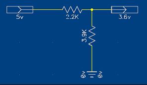
The output of this circuit will be dependent on the load but should give around 3.2v – 3.6v when driving a TTL type load, well within the acceptable logic high range of the device. It does require higher amounts of current compared to some other possible arrangements and it will also continuously draw current when at logic high. But the amounts are tiny and probably only of concern when every micro-amp counts.
A simple transistor configured as a switch is possible, but remember that it would invert the logic levels, requires more components than a potential divider, and rising edges of the signal would be slower.
Another way to do level shifting is to use a component that’s capable at running at the lower 3.6v but will still happily accept 5v on its input, and the 74HCT range of IC’s are ideal. A 74HCT08; quad 2-input AND, provides four gates in a package that will do nicely for this purpose especially as it’s an AND gate so it won’t invert the signals (of course, you may need to invert the signals so a 74HCT00/ 04 would be ideal then). The IC’s power rails are connected to +3.6v as that’s the output voltage required from the gates.

Concerns with using a gate are component costs, power requirements and board space, plus you’ve got to get the IC gates in series with the signals you are trying to shift, possibly making the design more complex.
Therefore, we’ve managed to step-down the 5v to a more acceptable 3.6v, but what about going the other way. Here, again you have several options.
Stepping up.
Firstly, you can do nothing. The PIC in this example will happily see the 3.6v applied to its input pins as logic high, so actually you don’t need to do anything. If there is a real need to shift the voltage level up, then you could do the reverse of figure 2; power the IC from 5v but feed 3.6v into one of the gates inputs and pick up 5v on the output. If you check out the specification for the IC’s in question you will see that 3.6v is above the minimum voltage required to generate a logic high state.
The above suggestions should work fine with SPI or any other unidirectional signals.
However, if you were using I2C or some other bidirectional signals, then you would be better looking at some of the specialist components designed for this job, and there’s a great application note AN97055.pdf that offers help with this problem.
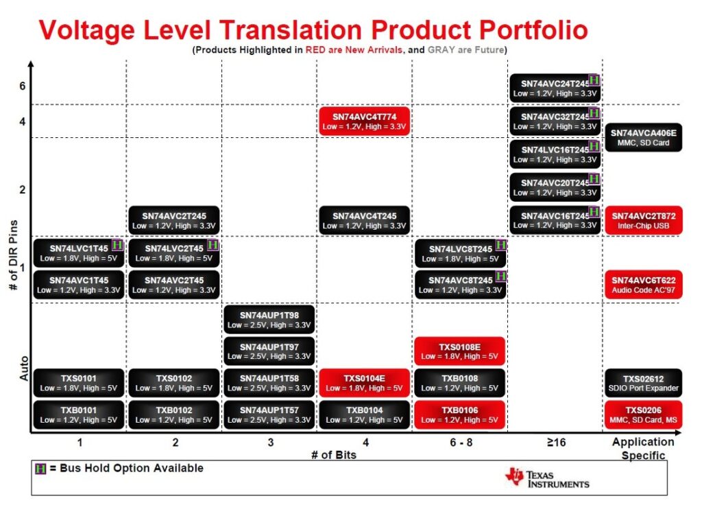
Below is the Texas Instruments device voltage level portfolio:
As a hobbyist you may well use “jellybean” 74 series ICs and they are available in many different series; LS, HCT, ACT etc, and they are not all compatible with each other.
The below table shows the compatibility between the different 74 series.

Leave a Reply
You must be logged in to post a comment.