

Back in the mid 70’s when I’d not long started playing with electronics I stumbled across the advert from the British National Radio & Electronics School. It promised to teach you electronics and as part of the course work you would build a working oscilloscope. My brother had one and he’d used it many time to show me what was happening in my circuits and why things weren’t always working as I expected, I wanted my own really badly. It turned out he also had done the same course some years previously, so I set about pestering my father to pay for the course. He gave in eventually and after a few months and a fair amount of head scratching I had a working 2 valve (vacuum tube) oscilloscope. Ok, so it wasn’t a particularly good scope. Single channel, not calibrated (and impossible to calibrate), no trigger capability, could only measure AC signals and I would be amazed if it’s time-base was more than 1MHz; probably considerably less, but it was mine, it worked and opened up my world into what was really going on in circuits.
That scope served me very well till I started working some 10 years later and could afford to buy a higher quality one. I still have it… and it still works.
And that would be the end of my story, except….
A couple of years ago my brother passed away and I was charged with emptying his workshop. Like me, he had amassed a lot of stuff over some 50 years and whilst boxing everything up I came across this little gem.
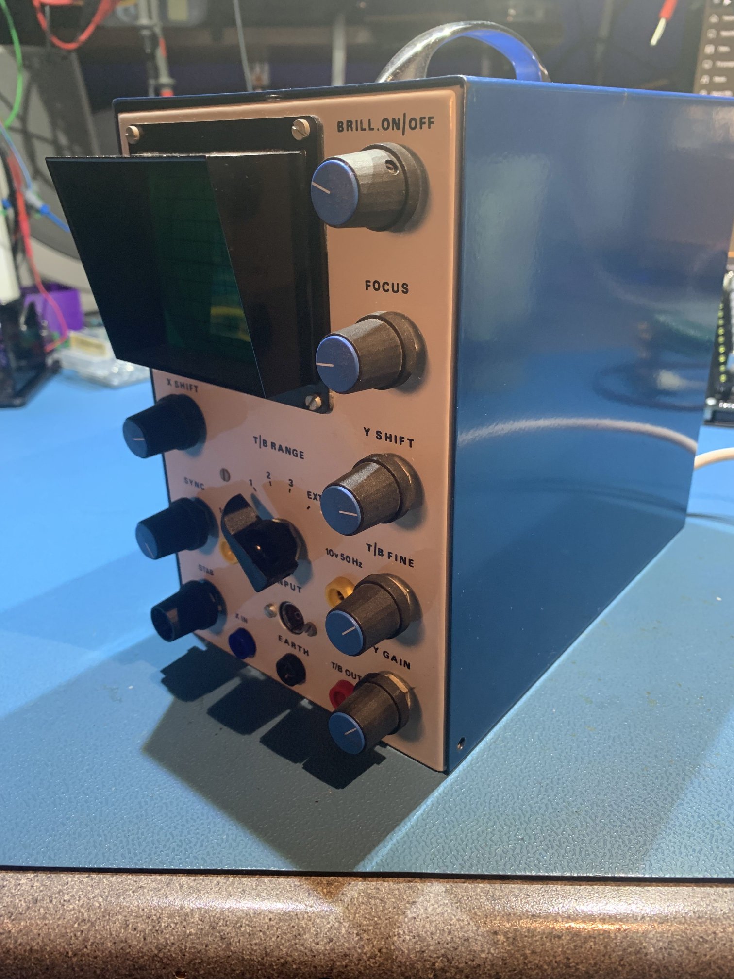


From the outside it looks basically the same as the original one in the advert above, but inside it’s very different. It took some research but I eventually found out that the company updated the design to be completely solid-state; with the exception of the CRT of course.
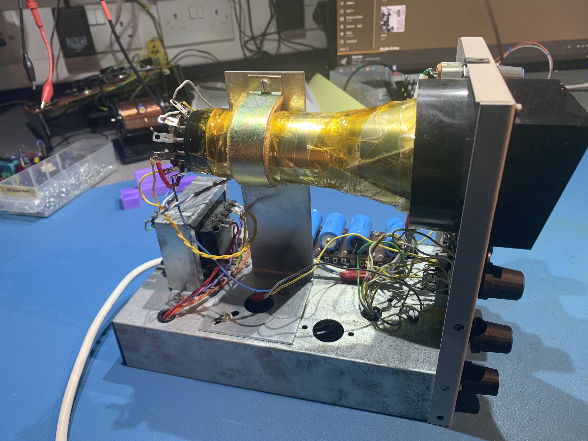
Basically they had used the same chassis as the original but stripped out all the valves and replaced them with… well… we will come on to that.
I rather liked the original valve version, but the new version is, in my humble opinion, horrible. Being solid state is an improvement and from what I can gather the performance would be similar to the original, but the way it is assembled internally is terrible.
Now I suspect my brother bought this; probably from Ebay, for the nostalgia and as a bit of a fun restoration project and I’m also assuming he never got around to repairing it because after an initial safety inspection I plugged it in and it didnt work.
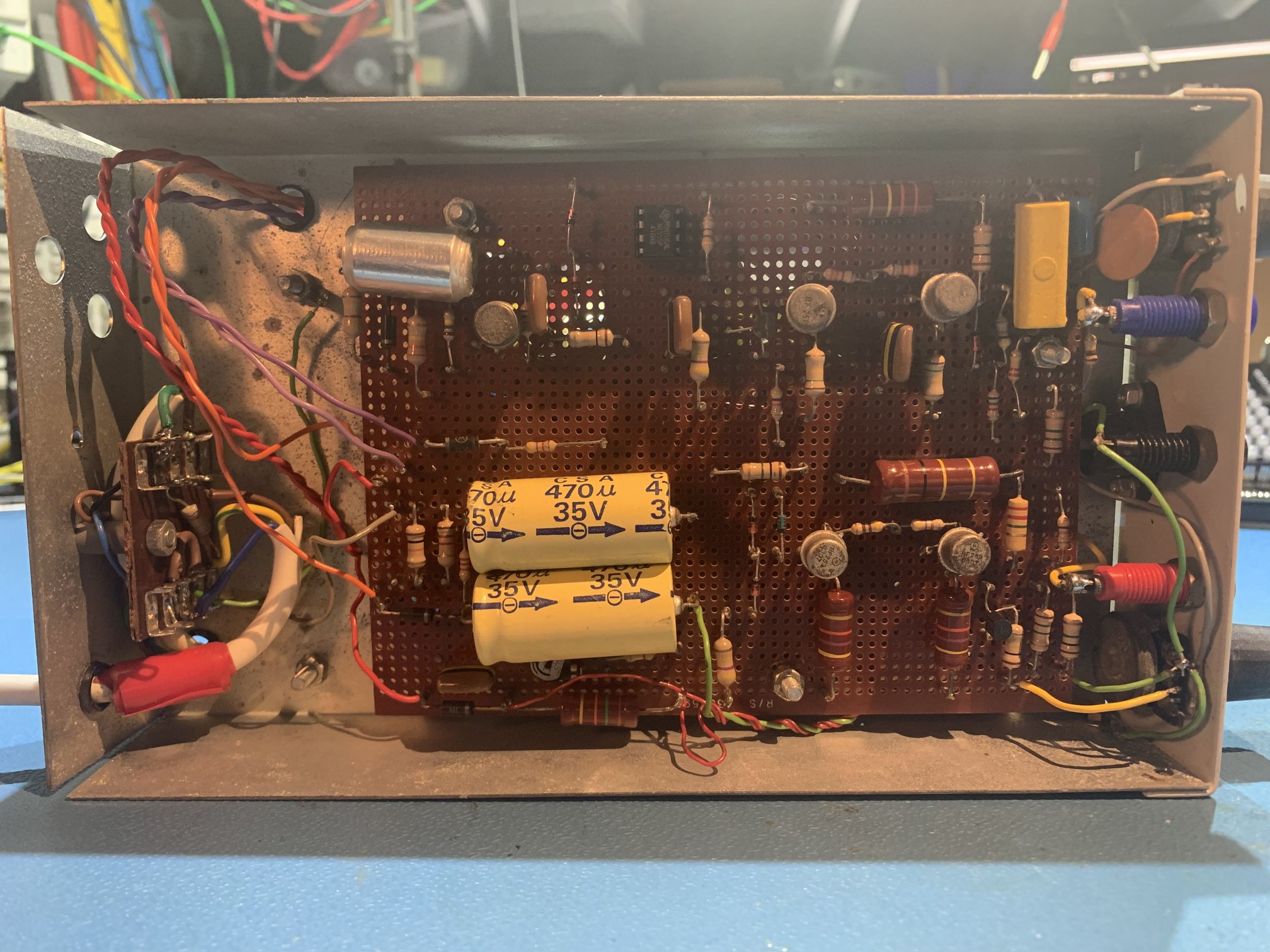
Step 1 was to have a look around and see if there was anything obviously wrong. Now the problem with this project is that it’s supposed to be built by somebody who is a beginner and knows absolutely nothing about electronics, and that leads to…. well lets just say poor quality of construction. We’ve all got to learn somewhere of course, but it makes fixing the thing difficult. Also, the design is less than ideal. You can see that the main circuit board is mounted on the underside and there is no easy way to remove the board for inspection as there are a lot of wires soldered to it. The board isn’t a PCB but a piece of standard matrix board. Vero pins are pushed through the holes and there are interconnect wires soldered to the underside. On the topside all the components are soldered. Wires that connect to the controls and other parts of the chassis are soldered to the top and bottom sides of the board.
Anyway the soldering of component leads to the pins looks suspect for most of the joints, so with a pair of needle nose pliers I started to gently tug on component leads and hey-presto, several were lose or just came off with the slightest tug, and after some re-soldering of the failed and suspect joints, I powered on the scope and it worked… sort of.
So it powers up and displays a typical flat trace, but the the Y-amplifier doesn’t appear to be working as you cannot move the trace vertically and it won’t display an input signal. There are also some “calibrated” output voltages via the two yellow 4mm sockets on the front and they are way out of spec. This scope still has a lot of problems. Not a problem, time to find the documentation and refer to the circuit diagram, and that’s where the wheels fell off my great repair effort.
More soon.
Leave a Reply
You must be logged in to post a comment.