
The humble 7805 and associated family of linear voltage regulators have been in wide use for many years. When they became available to the hobbyist in the 1970’s they were a bit pricy but with the addition of a couple of cheap capacitors they meant you could build a pretty good and nicely regulated PSU in a compact space.
They are somewhat frowned upon these days as they are not very efficient, that said they are about the cheapest and simplest way to generate a known (or variable if required) stabilised voltage. With their in-built short-circuit and thermal protection they are also almost indestructible.
I said they aren’t very efficient and the reason for this is that for them to work correctly, the input voltage must be a couple of volts higher than the required output voltage. The exact value of this “head” voltage should be checked on the manufactures datasheet.
Rule 1 – Check the manufactures datasheet for the exact device you are using.
For various reasons, all manufactures think they know best and so the specifications can change between manufacturers.
Rule 2 – Really do check the manufactures datasheet
Ok… I’m repeating myself for a reason here. The 78 series voltage regulators are designed to work with positive voltages. There is also a complementary 79 series of negative-voltage regulators.
If you hook up a 78 series regulator correctly and follow the manufactures directions in respect to input voltages and capacitors, you can happily place a volt-meter on the regulators output and see the nice steady voltage being produced; usually around +/- 0.1v of the specified voltage.
The 79 series are different from the 78 series as for one thing, the pin-outs are different. However, connect up a 79 series regulator (observing the different pinout) and measure its output voltage and you may get a nasty surprise as the voltage will be MUCH higher than you expect. One clue is the datasheet with often states the output voltage with a minimum load (often around 5ma) applied to the regulator. The same is often stated in the 78 series regulator datasheet as well though it seems less of a problem with these devices.
Efficiency
The voltage difference between the input and the output has to be “disposed” of somehow by the regulator, and this is done though heat and the higher this voltage difference and the higher the load placed on the regulator, the more heat is produced. This heat is a waste of energy (and the source of the inefficiency) and can also be troublesome to deal with, requiring the use of large heat-sinks and sometimes fans; which require power in their own right adding to the overall inefficiency of the project.
Rule 3 – Place the decoupling capacitors as close to the regulator as possible
The datasheet will tell you the recommended values for the regulator decoupling capacitors. My personal preference are two 0.1uF (100nF) caps as close to the regulator input and output pins as possible. Without these the regulator may start to oscillate or do other strange things.
Rule 4 – No high value electrolytic on the regulator output
It often feels counter-intuitive not having a nice large electrolytic capacitor on the regulators output. It’s gone to all that trouble producing a nice regulated voltage so it makes sense to have a reserve available for the circuit peek demends. However, regulators really don’t like it, and there is no need. They are designed to react rapidly to change in demand. However, a nice large reservoir capacitor as close to the regulator input as possible is always an excellent idea. I stated previously that the 78/79 series regulators are almost indestructible but they do have one Achilles heel. If the voltage on the regulator output pin rises higher than the regulator input voltage, the IC can be damaged or destroyed, so this is another reason not to have large capacitances present on the regulator output.
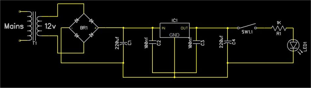
At first glance you may not see anything wrong with this, however notice C4.
When mains power is switched off from this circuit it’s possible, especially if SW1 is open, that C1 could discharge before C4 (the regulator is a drain on C1 where there is no load on C4 with SW1 open), meaning that the output pin of the regulator is now of a higher voltage than its input pin. You may get away with this for a while, but is bad design practice and will probably cause the regulator to fail at some point.
Another common application is in the construction of test equipment; typically that of bench power supplies. A situation that should always be catered for is a voltage source being connected to the power supplies output by mistake. Imagine a simple battery charger arrangement. The output of the PSU is connected to a battery being charged. The power to the PSU is then switched off but the connected battery starts to back-feed voltage to the output of the regulator.
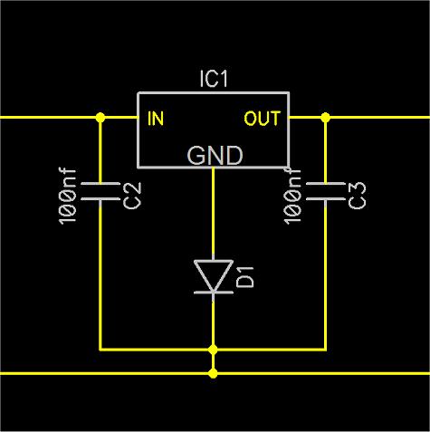
Fortunately there is a simple solution to this. A power diode (1N4001 for example) connected across the regulator will protect it in these situations.
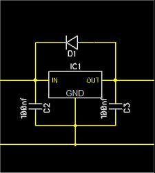
Figure 2 shows the inclusion of D1. In normal operation D1 is reverse biased but if the regulator input voltage, connected to the diode Cathode should fall below the Anode then the diode will conduct. This affectively bypasses the regulator protecting it. For the cost of a cheap diode, it’s often worth the peace of mind adding this extra component even if you are not expecting problems.
The question around C4 and large electrolytic capacitors on the output of regulators remains.
The voltage regulator is designed to regulate the raw input DC, and provide a stabilised (regulated) output at the desired voltage up to its maximum working amperage, if suitably heat-sinked. For the regulator to function
correctly, the input voltage must be reasonably well smoothed and this should never be skimped on.
But capacitors are fairly expensive and bulky so it makes sense to use as few as possible. Electrolytic types are also sensitive to their maximum working voltage; and the higher the working voltage, usually the more expensive and larger the capacitor. A 10v 1000uF capacitor is likely to be smaller and half the price than a 35v 1000uF variant… sometimes.
Reservoir Capacitors
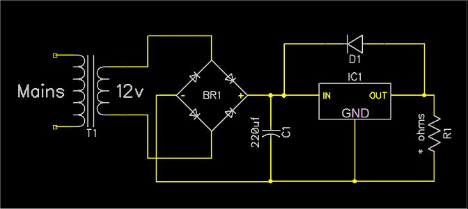
Using the circuit on the left, I performed some experiments to see how well the regulator would behave in certain conditions. I wanted to demonstrate this without having to bog the reader down in all the complicated maths that can go with this.
Notice that I’ve included D1 as during one of the experiments I managed to fry the regulator.
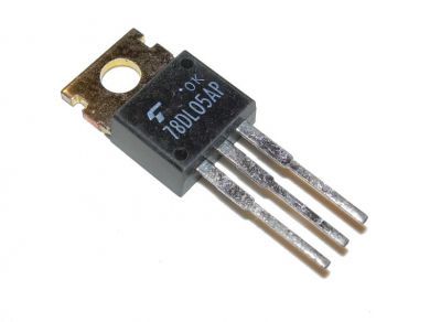
The regulator is a standard 1 Amp 7805 5v variant from Texas Instruments.
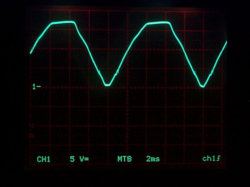
This shows the output of the rectifier without any load or reservoir capacitor. Even though the output of the rectifier is DC, the waveform still looks like a sine wave because without any reservoir capacitor, the rectifier output is directly proportional to the AC input voltage.
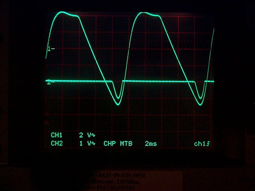
Changing the value of R1 to 10 ohms will present a load of around 500 mA to the regulator – 50% of the regulators maximum rated output and the effects of this can be seen in the above trace.
The regulators output voltage dropped to around 4.87v during this test.
Remember that the reservoir capacitor is designed to smooth out the peeks and troughs of the DC from the rectifier but because the load on the
regulator is now so great, the reservoir capacitor can no longer meet the demands being placed on it.
The regulator is unstable and is allowing its output voltage to drop by around 1v. If the load were to be increased, the voltage drop would get worse.
The solution in this case is simple; increase the size of the reservoir capacitor.
When the reservoir capacitor is exchanged for a larger 470uf / 35v component, the regulator output again returns to a steady voltage though you can see that the regulator input voltage is varying much more than before. The regulator output voltage was around 4.94v during this test.
The above shows how important it is to have a suitable reservoir capacitor for the regulator.
Previously I mentioned the size and working voltage and hence cost of larger reservoir capacitors, and suggested it may be possible to place additional capacitors of a lower voltage; so cheaper, on the regulators output.
The main reservoir capacitor was switched back to a 220uF, and a 470uF was placed across the regulator output.
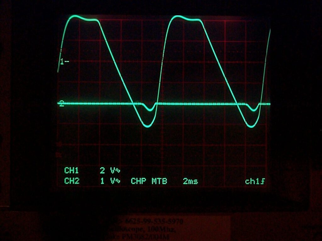
As can be seen the output of the regulator under the same 500 mA load is no longer stable. The voltage drop is less, but still unacceptable.
The regulator voltage fluctuated around 4.91v during this test.
Reservoir Capacitor Conclusion.
Reservoir capacitors should be placed on the regulator input side. They should be rated at least 25% higher than the maximum expected regulator input voltage, and should be of sufficient capacitance to make sure that when the regulator is under the maximum expected load, its output voltage remains stable. Electrolytic capacitors also have a ripple current value. The higher the current draw across the capacitor, the higher the ripple current. As a rule of thumb, if a regulator circuit I design is expected to provide more than 1A it’s time to check the datasheet for the reservoir capacitor(s) I’m going to be using to make sure they can handle the expected ripple.
Regulator overheating
As previously stated, linear voltage regulators can put out a lot of heat if there is a large voltage difference between the input and output, and/or the regulator is placed under even a modest load.
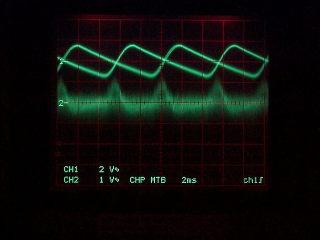
The 78/79 series voltage regulators do contain thermal protection and I thought it would be interesting to show what happens to a regulator that is stressed to the point of thermal shut-down.
In my test, a free standing regulator temperature started out just under 20 degrees; ambient temperature.
With a 500 mA load, the regulator temperature quickly rose to around 40 degrees and then its output voltage fell off to around 1.4v and you can see from the trace on the left, the regulator output (CH2 lower trace) is now extremely unstable.
I left the regulator running like this for around 60 seconds and then switched off the load. Within a second or two the regulator recovered back to normal operation.
So, it makes sense to reduce the input voltage to the minimum required to allow the regulator to function correctly, whilst maintaining a stable regulated output.
Regulator tips and tricks
One trick you can use is to slip one or more power diodes in-series with the regulator voltage input pin. Each diode will drop around 0.6v and this can make a difference to the regulators efficiency. You do have to be careful because as the current draw increases the diodes voltage drop can rise and you don’t want the regulators input voltage to drop below the minimum required voltage. The plus side is that as current demand on the regulator increases and so it would normally produce more heat, the series power diode(s) cause the voltage to drop more thus helping to reduce the heat being produced.
Power diodes can also be smaller and cheaper than large high-wattage power resistors in some applications.
Uplifting the regulators output voltage
Here a diode is placed in series with the regulators GND connection which will uplift the regulator output voltage by around 0.6v; useful if you’re trying to push a 5v regulator to around 5.5v or to perhaps cope with longer cable lengths. Be carful though as the metal tab on the 78 series regulators is connected to ground so it needs to be insulated if mounted to a metal case.
This is NOT the situation with the 79 series regulators where the metal tag is connected to the input pin
- Note. Some datasheets are absolutely terrible and explaining where the tag is connected. When checking for this paragraph I ended up checking the 7905 datasheet from ISC. It makes no mention of where the tag is connected. This could be an expensive oversight on your behalf. Check the datasheet and assume nothing !
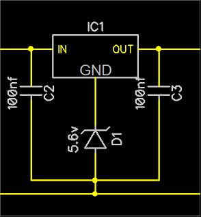
Here a 5.6v Zener diode in placed in series with the regulators GND connection. This will uplift the regulator output by around 5v, so with a 5v regulator will allow its output to rise to around 10v. A 10v Zener would allow a 5v regulator voltage to raise to around 15v. This can be a useful trick if you don’t have a regulator of the correct voltage.
- Zener diodes are not know for the voltage tolerance. You could try several diodes of the same voltage from the same batch and get different results. Measure the output voltages carefully !
Leave a Reply
You must be logged in to post a comment.