
The keypad went though several design iterations before I got something I was pleased with.
The initial PCB design was flawed in several areas and whilst it worked and was invaluable for getting the system running, longer term it needed to be updated.
I decided not to include the cassette interface as I can’t imagine why I would want to use that in the 21st century. That said, I did included a connector on the bottom right so that a separate cassette interface could be added if I changed my mind. Actually, my thinking was that I may try and use some type small flash memory boards for data storage and retrieval. The Monitor firmware would need to be updated of course, but it would be better than magnetic tape. However, that’s a future project.
I wanted a power LED… everything should have a power LED… I also elected to relocate the NMI and IRQ buttons that are on the original CPU board to the keypad; it just seemed sensible to have everything in one place.
The poor decision I made to Molex connectors for the ribbon cable connection needed to be corrected. They were all I had a the time and I tend to use them for everything. However, 22 pins worth of connector is a lot and it proved very difficult to detach the ribbon cable and on several occasions the pins were yanked from the Molex shell. The next version would use something more suitable.
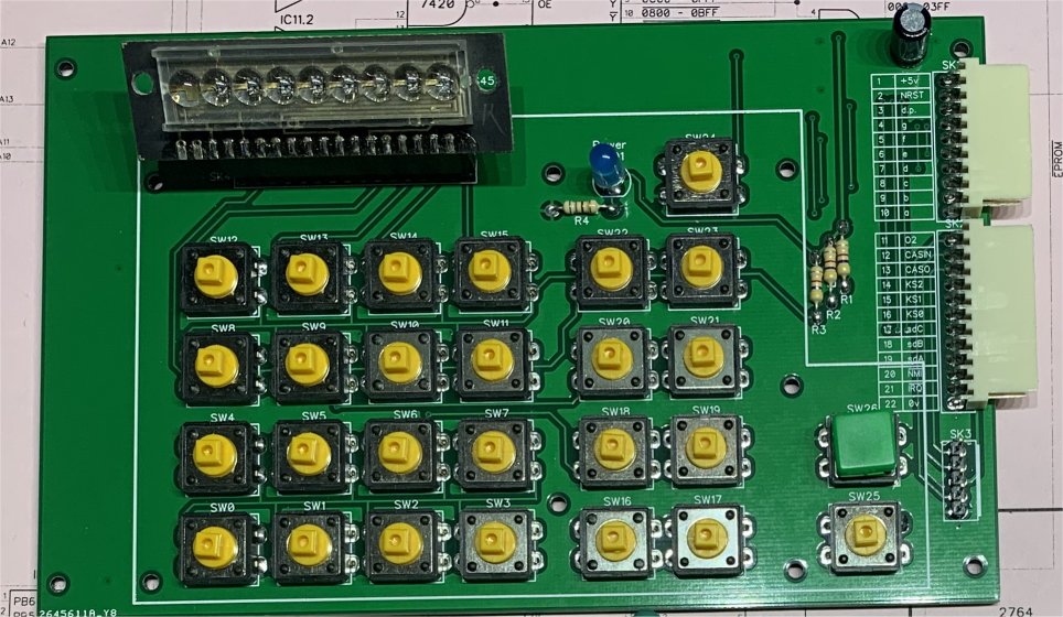
The above image is the final PCB design and included some fundamental changes over my first version. Firstly the ribbon cable connector has been relocated to the other side of the board and is now an IDC connector. Much easier to insert and remove and to assemble for that matter.
I’d previously added a header to connect to the bubble LED display (they are hard to find and I wanted to minimise the change of damaging it so decided to solder a header socket and make it removable, which turned out to be a good decision. I added two extra pins to the PCB header plug to provide +5v and 0v to the display. During testing I’d realised that when using the new W65C22 VIA chip, the bubble LED display was very dim; usable in a lit room, but only just. I decided it would be sensible to support a larger LED display, using more readily available 7-segment displays, and to do this buffering and drive electronics would be required. Because I didn’t want to add these extra electronics to the keypad, this meant that the display PCB would need to house the electronics and so would also require power, hence the extra power pins being added to the header.
I 3D printed a plastic keypad fascia in the hope this would keep the switches in alignment and looking nice. It wasn’t entirely successful; and I only had purple PLA filament handy. It worked but I really wasn’t happy with it.
As it happens I would end up purchasing a laser cutter for another large project and this allowed me to fabricate a keypad I would eventually be happy with.


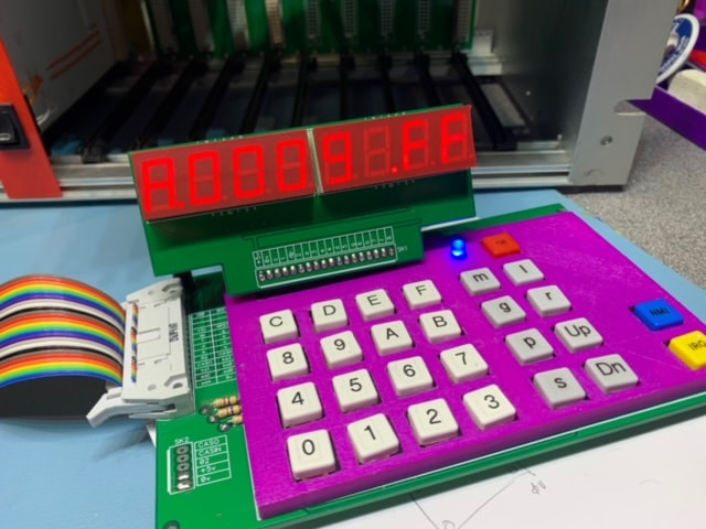
The above image shows the original official Acorn keypad on the left and my final version on the right. I have to say I’m pretty happy with the look and feel.
I didn’t want to change the PCB design again so needed my keypad surround to fit on the existing version.
Using a piece of black 3mm acrylic, I laser cut the key switch holes. I then applied a couple of coats of acrylic primer spray, then several coats of white enamel spray. Once dry, back into the laser cutter but this time set to engrave mode, I engraved in the lettering. This burns away the white paint leaving the black acrylic showing through to form the legend.
Next I needed to make the keycaps. This took me ages, mainly because on a couple of occasions I glued my fingers together.
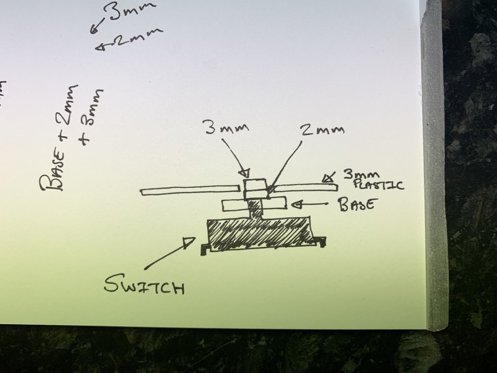
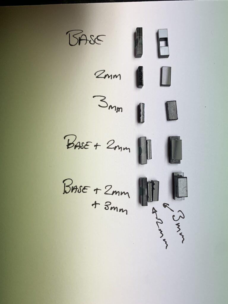
Using what I had available and working within the limitations of my laser cutter I came up with the above design. The plastic of the fascia was 3mm thick. A bit of experimentation with how much travel the PCB switch required to make a positive “click” showed it needed around 2mm. This mean a key cap needed to be around 5mm thick. My laser cutter can handle this, but I didn’t have any material that thick on hand so decided to cut a 2mm and 3mm piece and glue them together. Below you can see the three parts of the keycap and how they are assembled.
I needed to make 27 of these keycaps and cut sufficient to make 40 which was lucky as not all the parts made the grade. A couple ended up being deformed at the edges, some got dropped on the floor never to be seen again, and some… well I don’t know what happened to them but I ended up making around 30, then chose the best 27 from them.
You can see that the base part has a square cut in it. This fits snugly over the shaft of the PCB switch and holds everything in place. I then fixed metal spacers to the keypad PCB via the mounting holes on the base PCB and dropped the cut fascia on top. It took some experimentation to get the correct height spacer but I managed it. Finally I removed the fascia, added a few drops of glue to the top of each spacer and carefully lowered the fascia back into position and allowed it to dry.
Top tip – I used metal hex threaded spacers. I’ve got a box full of them in different sizes and they are great for jobs like this. Pop a small M3 6mm screw through the bottom of the keypad PCB and screw the spacer onto that. However, once you’ve done this get a tiny little piece of paper and stuff it into the hole at the top of the spacer. This will prevent the glue running down the inside and gluing the bolt thread to the spacer preventing you from getting the darn things out again, and it soaks up the glue giving a larger bond area to the underside of the fascia.
Second top tip – Remove the retched protective plastic from the plastic before cutting the keypad parts. Once you’ve got a stack of 100 tiny bits of plastic it takes forever to remove the protective plastic.
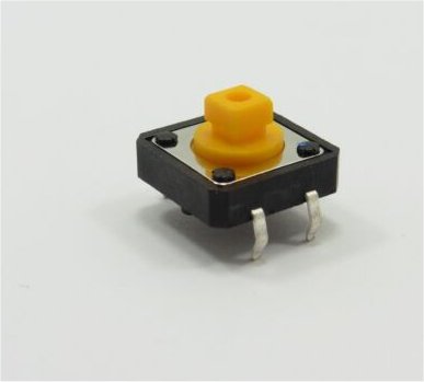
The switches were from Ebay and are 12mm x 12mm x 7.3mm square tactile push switches. Ebay seemed awash with them and they are pretty cheap and give a nice tactile “click” when pressed.
I’ve included the BEAMO laser cutter files for those that have access to one of these machines that will allow you to cut a fascia and keycaps. There is a version for the rectangular keycaps I’ve described above, or square holes for using the supplier keycaps that fit these PCB switches.
Construction details, schematics and plans can be found here.
Leave a Reply
You must be logged in to post a comment.