
The System 1 starts out as two euro cards stacked one on top of the other; CPU at the bottom with Keypad/Display on the top. It’s nice, compact and very pretty, but rather useless as soon as you want to start hooking it up to things. Quickly you realise that you are going to need some type of backplane to plug your expansion cards into, a regulated power supply that can supply all the different voltages you are going to need; some at a fairly high current, and probably a nice box to put it all in and keep it safe, and the 19″ card frame rack is ideal for this.
As luck would have it I’ve several 19″ card frame racks lying around the workshop that came form all over the place, are from different manufacturers and in various states of repair. But they have the critical components needed. They are metal, have card guide rails… actually that’s about it. Oh, a couple have handles on the front.
The 19″ card frame rack is 19″ long, 3U high and deeper than an Euro PCB card (which is 100mm high by 160mm deep), and there is usually provision to mount a PCB along the back to form the backplane. It should also support card guide rails. These can be individual rails and snap into fixing holes, or a continuous moulded section that screws into the top and bottom and has the guide slots cut into it.
From this point on you are free to do this however you feel most comfortable and utilising what junk you have or have access too. I have over the years made several racks for computers and other projects and I have a pattern I work too that seems to work for me.
Step 1 Mount a power supply.
A standard PC power supply is ideal for this project. It has multiple voltage outputs (5v, 3.3v, +12v and often -12v and -5v) with the +Volt rails usually capable of supplying eye watering amounts of current… more than enough for this project anyway. Again I tend to always follow the same pattern. I slip the PSU into the rack, mains socket with power switch at the front, and all the low voltage cables out the back. There are usually convenient fixing holes in the PSU that can be used but be very carful if you find you need to drill into the PSU chassis; there is never much room inside and you will damage something if you aren’t extremely carful. Best thing to do is fabricate a couple of straps out of some scrap aluminium or at a real push you could use long cable ties. Just make sure the PSU is mounted firmly.
Step 2 Backplane.
Once the PSU is mounted you can then see how much room is available for the backplane.
Now you need to be carful here and don’t rush this part. You are probably going to get PCBs made for the backplane. The larger the PCB the more expensive it is. Also, JLCPCB which I always use, always supply a minimum of five identical boards and I really don’t need five, 10 slot backplanes. It may be better and cheaper to design 5 slot backplanes and join two together or some other size as suits your needs. Smaller is cheaper!!
There is one other thing I like to do.
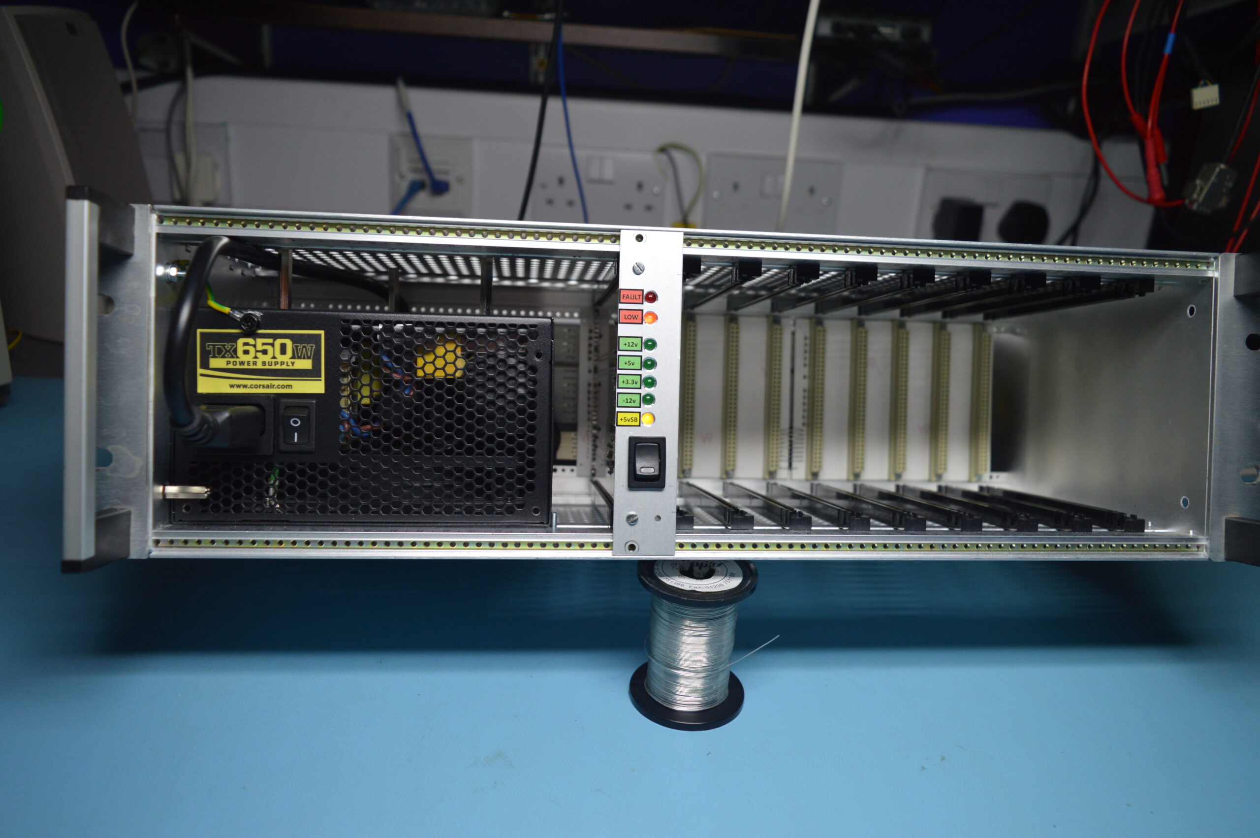
The above rack is from a different project but shows the layout including the PSU controller board.
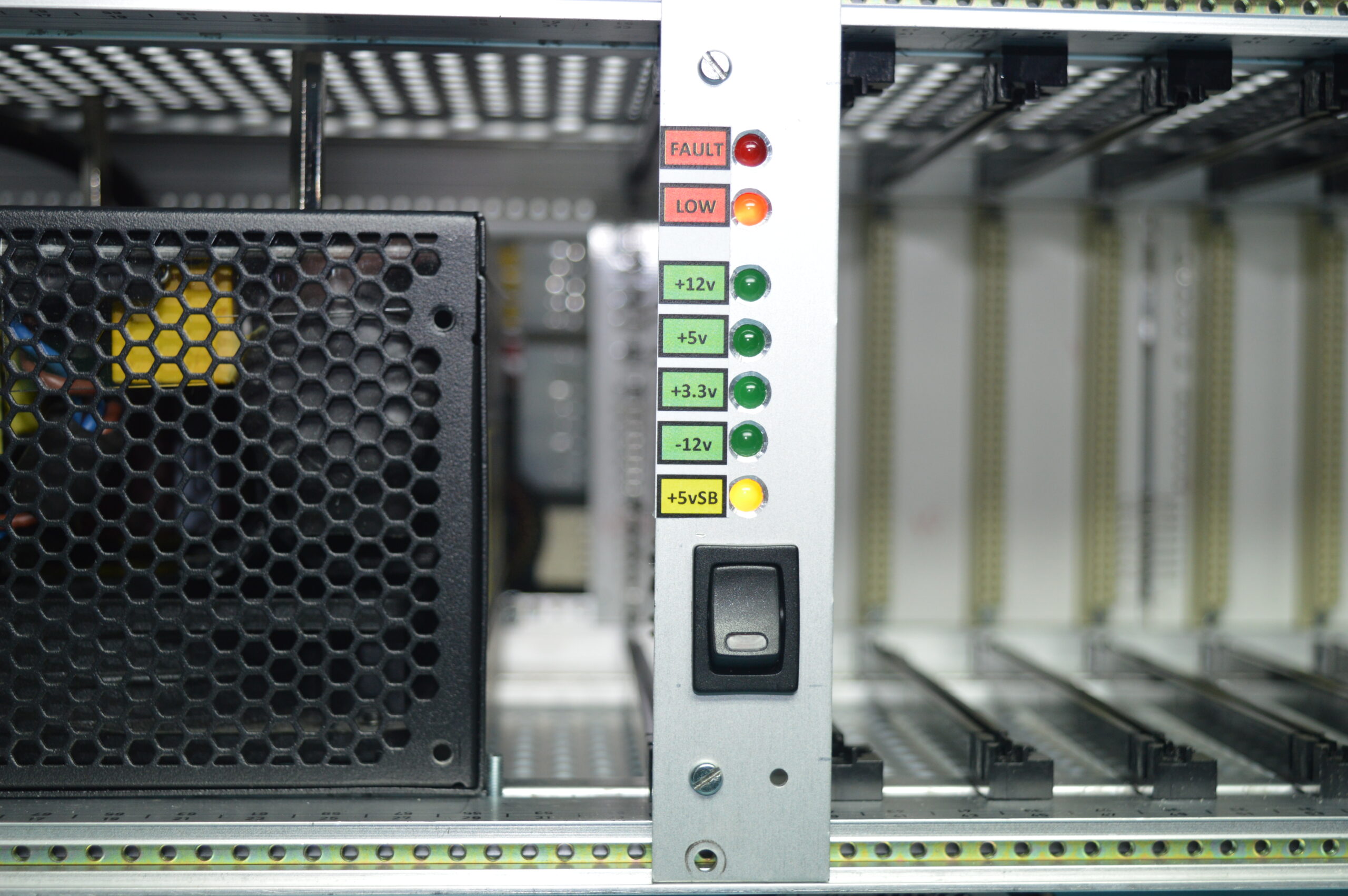
If you’ve ever used a PC PSU for your own projects you will know that most of the time you can’t just plug it into the mains and watch it spring to life. Typically, as soon as power is applied the USB5v power rail will become active, but most of the PSU will remain dormant. There is a sense input to the PSU that needs to be grounded before the PSU will attempt to turn on. Some PSUs also need to detect a load on the +12v or +5v rails or will immediately shut down again. This feature is PSU make/model dependant it seems. There is also a Fault signal from the PSU that can be useful to monitor. Rule of thumb is either read the PSU’s datasheet… or at least read at the label on top.
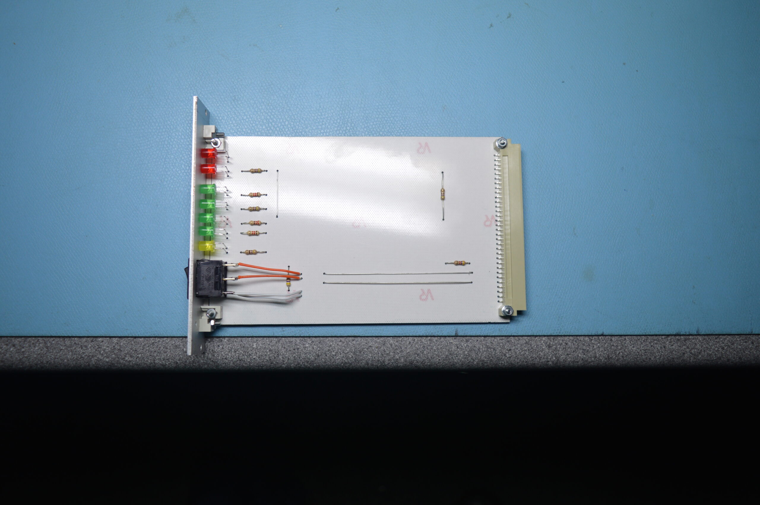
So, in my racks the first available slot contains the PSU controller board. It’s really just a switch that can trigger the PSU sense input, and a set of LEDs to monitor the various output voltages and Fault signal. It plugs into a single slot backplane that consists of Molex connectors. The design files are listed the end of this post.
So now you’ve got your PSU mounted in the frame, fitted the PSU controller single slot backplane and should be able to turn the PSU on and off meaning that whatever space left is available for your project backplane.
If you’re working to a budget you need to think what type of expansion cards you will be wanting to house in the frame. Memory boards, some simple I/O boards, maybe a VDU card… all of these probably only need a single slot. You may want to create an EPROM programmer, or possibly a sound card with integrated audio amplifier and speaker, or something with an LCD display or perhaps multiple 7-segment displays and these modules will probably be wider than a single slot; possibly 2, 3 or 4 slots wide.
What all this means is that you may not need to have a connector at the rear of each slot.
What I would suggest is that you create and mount a backplane that spans the entire available space in your frame; typically around 10 slots after you’ve mounted the PSU and controller card, but you don’t populate every backplane slot with a connector. I often populate the first 2 or 3 positions on the left, and then the right most position. As I create modules I add more connectors in the correct positions.
When designing your backplane you need to be very carful with the mounting hole positions. I was lucky in that I had a couple of frames that were identical, but my backplane boards won’t fit correctly in another frame I have, as the mounting holes are all in completely different positions.
Design your backplane and print the PCB foil out on paper and stick that to a piece of card; the type of card you find on the back of a writing paper pad is ideal. Cut it to size, punch/drill out the mounting holes and then see if it will fit your frame. You can then adjust things as needed without getting expensive boards made only to end up in the bin.
I will include my standard 1+9 slot backplane that I use for many of my projects, but be warning this is a completely passive backplane and would not be suitable for use with real Acorn System 1. The proper System 1 backplane has provision for buffering and has some other features that are not present on mine.
You will see that the 9 slots only make use of the +5v rail. That’s because this frame is designed to house logic boards. Some projects have a second peripheral frame that I mount disk drives or whatever in so I run a nice thick cables from the large Molex connectors behind the PSU controller card up to this peripheral frame. This peripheral frame may, or may not have it’s own backplane.
Leave a Reply
You must be logged in to post a comment.