
In this thrilling instalment we shall look at the 8 bit LED display card.
This card is probably the simplest expansion card there is. It contains eight LEDs, and you can display any value from $00 to $FF by writing to a specified address. The address is specified on the card.
The initial version of this card contained all the address decoding to effectively decode a single address, and it was at this point I realised that every card in the system would need address decode electronics and this is the revelation that led me to designing the SAD expansion card.
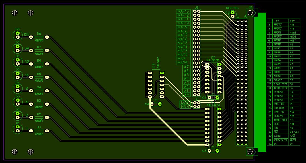
As can be seen, the design is pretty simple.
There are 8 x LED’s on the left, one IC performs the address decoding, one IC acts as an 8-bit latch, and there is a 3rd IC that I just use a single inverter from. I could have used a transistor for this but decided on an IC.
You can configure the MAP signal the board uses for the address decode, you then select which of the eight outputs from the 74LS138 to use, and an additional jumper lets you select either the high or low 8 bits of the 16 bit segment, and that’s basically all there is.
The boards I built had red LEDs, but you could use any colour or mixture of colours, and you can have as many of these boards in a system as you like.
This is a great board to use as a building block for your own designs. The board could be redesigned to drive (and latch) relays, or bulbs, or Thyristors or buzzers or anything else you like. It would make a nice general output card.
If you were to turn the 8-bit latch around and drive that from the CPU read signal instead of the write signal, you could then design an 8-bit input card.
The input card could have an ADC (Analog to Digital) converter installed and now it’s a card capable of reading a voltage. Likewise the output card could be redesigned to use a DAC (Digital to Analog) converter so that it can produce a configurable output voltage. The possibilities for these cards as part of a larger design are endless.
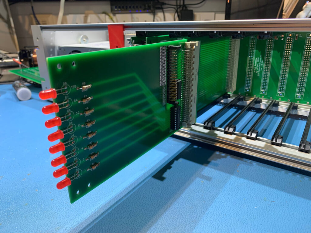
Here’s an 8-bit LED output card connected to a euro card extender and plugged into my System 1 rack. This was a prototype version that didn’t work as expected; hence the reason it’s plugged into an extender card so I could poke around the underside with my oscilloscope. The final version needed the extra logic IC and that pesky single inverter.
At this point you should have a working CPU board, Keypad & display, possibly a SAD card and LED display card and a 3-slot backplane with on-board PSU to hold everything together. There will be further articles as I get around to them detailing other expansion cards and hardware.
Construction details, schematics and plans can be found here.
Leave a Reply
You must be logged in to post a comment.