
Replicating the CPU board
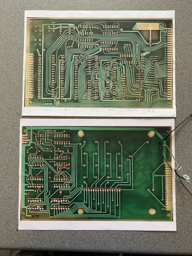
The first problem was to get hold of a schematic and make sure it was correct. On-line I found hi-resolution pictures of both sides of the two PCBs so printed them out, stuck them together and traced each track on the PCBs, comparing it with the schematic and there were a couple of differences so a new schematic was draw reflecting the differences.
Now I had what I believed to be a correct schematic I started to look at what changes would be needed.
The original system used 74571 PROMS; which I don’t have and even if I did, don’t have a suitable programmer for. There was provision to use a 2716 EPROM and whilst this is a bit more modern and I do have some, they use weird programming voltages and my EPROM programmer doesn’t support them.
I made some changes to the schematic to remove the PROMS and support a 2764 EPROM instead. I also realised I could use an EEPROM if required which is nice.
I dropped the original 2114 RAM chips (which I do have but aren’t particularly common) in favour of a a single 6116 which I have a lot of; though as it turns out these aren’t as common as I thought either.
What followed were a lot of design revisions and corrections resulting in some significant updates.
- I decided to not use the original 6502 CPU and instead moved to the more modern W65C02 variant. I did this as it allows for single stepping though programs easily (the registers in the original 6502 were not static and their contents could be lost if the clock was stopped). Also the W65C02 can be clocked at a much higher speed (this project supports up to 8MHz but it can run faster) than the original 6502’s 1MHz.
- I replaced the 6116 RAM (that had already replaced the 2114 RAMs) with a 6264. Whilst the CPU card can only utilise up to 2K of the possible 8K, the 6264’s are more available and cheaper than the 6116s.
- Because the W65C02 could be clocked significantly faster than the legacy 6502, I made provision for a faster clock but with configuration jumpers so the board clock speed could be specified by the user. With an 8MHz XTAL on the board, you can select 8MHz, 4MHz, 2MHz, 1MHz or 500KHz clock speeds. You can of course use a different crystal and jumper settings and run the CPU at anything from DC to 14MHz (max CPU speed). However, the TTL logic, RAM and EPROM are only good to around 8MHz.
- I replaced the INS8154 with the W65C22 IC. This is rated at much higher clock speeds than a traditional 6522 and complements the CPU running at 8MHz nicely. You MUST use the W65C22 VIA if you intend to run the CPU faster than 1MHz as the standard 6522 just isn’t fast enough. Also the INS8154 is very difficult to find and if you do find one, expensive. The original has provision for two of these ICs but only one is actually needed to make the system run. I will only allow for one VIA replacement onboard.
- Some additional configuration jumpers were added to the PCB, the original configuration jumper block had to be tweaked slightly and some additional control signals were routed to the 64 pin edgeway connector utilising spare pins.


At this point I’d now generated a final version of the schematic. As I say it went through a lot of revisions and design iterations to get to this point, but it works.
Leave a Reply
You must be logged in to post a comment.