
I’m currently working on a +5v plug-in module for my new PSU (see previous blog post).
I had several requirements for this module including the ability to withstand a dead-short circuit and the final output voltage to be trimable to +/- 0.5v. Because of this I decided not to use the existing +5v rail that’s already present, instead opting to down convert the existing +12v.
Good old linear regulators are almost indestructible if a few sensible precautions are taken, but they give off a fair amount of heat when dropping a large voltage, especially if you are wanting to pull a couple of amps.
After some research I opted for the LM2576-ADJ (also because for some reason I have a stack of them to hand).
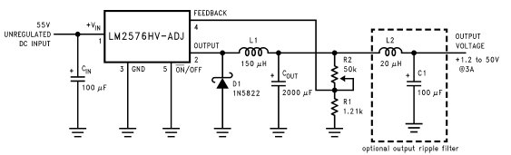
The above circuit is straight from the datasheet and I’m using this almost as is. The only component required that I didn’t have was the 150uH inductor.
Like most seasoned hobbyists I’ve learned to keep things that are useful and I’ve a drawer full of old inductors, ferrite rods and toroids that I’ve salvaged over the years but I decided to wind my own inductor on a ferrite toroid.
Now I’ve never really given this much thought before, but when buying inductors they list the inductance value, the amperage and sometimes the resistance. A wire inductor is after all just a long piece of wire, usually wound around a former of some kind so it’s bound to have resistance and the more wire you have, the higher resistance. Because it’s wire it has a maximum current carrying capacity and hence a maximum working current.
However, whilst experimenting with winding an inductor for this project I noticed something that in hindsight is obvious, but that I’d never really thought about before.
I wound two different inductors and after some experimentation managed to get them both pretty close to the inductance required; and I’ve opted to use a slightly higher value of around 220uH for this project.
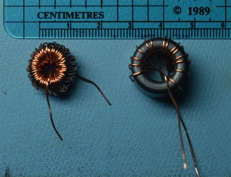
The left one was wound on a much smaller toroid; you can’t tell from the picture but the larger core is also around double the thickness of the smaller one.
Both inductors work in my test circuit but the larger one is more efficient.
With the input voltages the same for both tests, the regulator circuit draws 472 ma under test with the larger inductor, and 493 ma with the smaller one.
I’m not sure how many turns there are on the small inductor, probably around 70, but you can see there are only 14 on the large one and even taking into account the physical size of the core, much less wire was required and hence it has a lower resistance.
Oh, and if you’re wondering how I wind my cores and check their inductance, I’ll create a blog entry about that when I get a chance.
Leave a Reply
You must be logged in to post a comment.