
The long bank holiday weekend arrived and I decided I would complete a battery powered project that’s been sitting around for a while; I have a lot of half completed projects sitting around the workshop.
I needed to calibrate the software that monitors the internal rechargeable batteries and realised I didn’t have any type of suitable data logger. So a nice quick little project idea was born, and anything to distract me from what I should be doing.
Whilst trying to calibrate my new little data logger I realised that my trusty bench PSU drifts around, a lot.
I built it around 10 years ago and it does the job, but it’s a bit limited. I also think that the reservoir capacitors could do with being replaced. Also the always on fans are a bit noisy sometimes.
So, the data logger project got dumped on the growing pile of half completed projects and I set about designing a new power supply.
I’ve been thinking about doing this for a couple of years, and I’ve even been slowly acquiring the parts required.
The problem I’ve found with bench PSU’s is that they never do everything I want. Some fixed 3.3v, 5v and 12v outputs that can supply a couple of amps each would be nice. Then I started experimenting with Nixie tubes and realised I needed something that can produce a couple of hundred volts at a few mA. Then I needed a 12v PSU that could supply around 10A to allow me to repair and test a CB radio for a friend. Then I wanted something that was suitable for battery charging. Now 1.8v electronics are starting to become popular and my bench PSU won’t go down that low. And the list goes on.
I decided I needed a modular PSU, one that I could plug in personality modules designed for specific purposes and hey presto, the universal modular power supply was born.
It can supply around 24 amps at 3.3v, 30 amps at 5v and a whopping 50 amps at 12v and has a single quiet, variable speed fan. It can also supply -12v at 1 amp. Pretty impressive I hear you say.
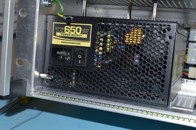
Ok, so I cheated a bit and based the design on a 650w PC power supply.
However, I’m NOT going to do what many of these cowboys do and just mod a PC PSU.
It’s dangerous and to be honest, a complete waste of time. I’ve seen many projects that start off by drilling holes in a standard PC PSU, fitting binding posts and then saying its a complete project, only for the PSU to fail (of old age or by your own actions) and you have to start again.
A bench PSU needs to be robust and capable of handling short circuits and other silly mistakes.
Current limiting is also an essential component when your PSU can deliver 50 odd amps in a heart beat.
The PSU I’m using is an unmodified (almost) stock PC PSU. The only modification is to cut off the low voltage connectors as I didn’t have suitable male connectors to fit. As it happens, it’s a neater job if you cut the cables to the desired length and use your own connectors and that’s it. You don’t even have to open it up or remove the lid.
My design is based on a 19″ Vero rack, and with the PSU fitted there are 10 card slots available for custom modules. The great thing is that if I run out of slots, I can remove modules that aren’t currently required or I could extend the unit to a second rack.
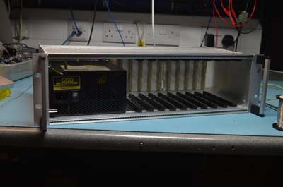
The above images show the completed frame.
You will notice from the first image there appears to be three metal spacers from the top of the frame to the PSU. These are just holding the PSU in place and stop it moving around. They are not fixed to the PSU housing.
You may also notice a couple “stop” in the bottom left of the picture that stops the PSU sliding forward and another one on the bottom right that stops the PSU sliding sideward. These stops hold the PSU really snugly and there’s no movement at all. Also, if I need to replace the PSU for a different size one, I can move the stops around as required.
I did add an earth wire from the PSU (using one of the PSU’s mounting holes) to bond it to the chassis and so scrapped the paint off the PSU to get a good connection.
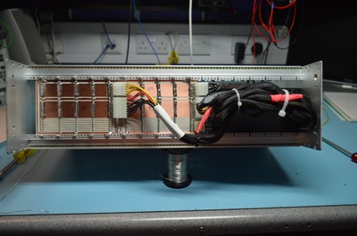
The backplane consists or two identical (well almost as I changed the design slightly for the second card to correct a minor mistake I noticed during drilling), five slot panels. Each panel is fed with +12v, +5v and 0v connections.
You can just see the control signal connector on the right panel in the bottom right corner that connects to the PSUs control signals.
There is a nice metal cover that screws on the back of this rack to protect everything, and whilst you can’t really see it from the pictures, the top and bottom panels are perforated so there is plenty of ventilation for the PSU and the plug in modules. The fact that the frame is metal will also mean it acts as a giant heat-sink.
As it happens, I probably won’t make use much of the PSU’s native 3.3v and 5v rails as there is no short-circuit or current limiting protection on these lines, so most of what I need will be driven from the 12v rail. However, some of the plug in modules may require a low voltage for some logic so using the existing 3.3v and 5v rails will save me some effort.
After checking for short circuits between the rails, I connected the PSU plugs and plugged in. As expected nothing much happened. The +5VSB line is active but that’s it.
The first module will actually be a monitoring and controller card. The PSU requires a dummy load on the 12v line before it will power up correctly.
Leave a Reply
You must be logged in to post a comment.