
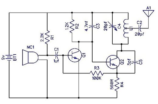
This article shows you how to build a very simple FM transmitter from thirteen components (one of these you make yourself), a Printed Circuit Board (PCB) and a 9v battery.
It should be mentioned that this unit will be illegal in some countries as it transmits on the FM band anywhere from around 70 to 180MHz, however, it puts out very little RF power and shouldn’t really interfere with anything or anybody.
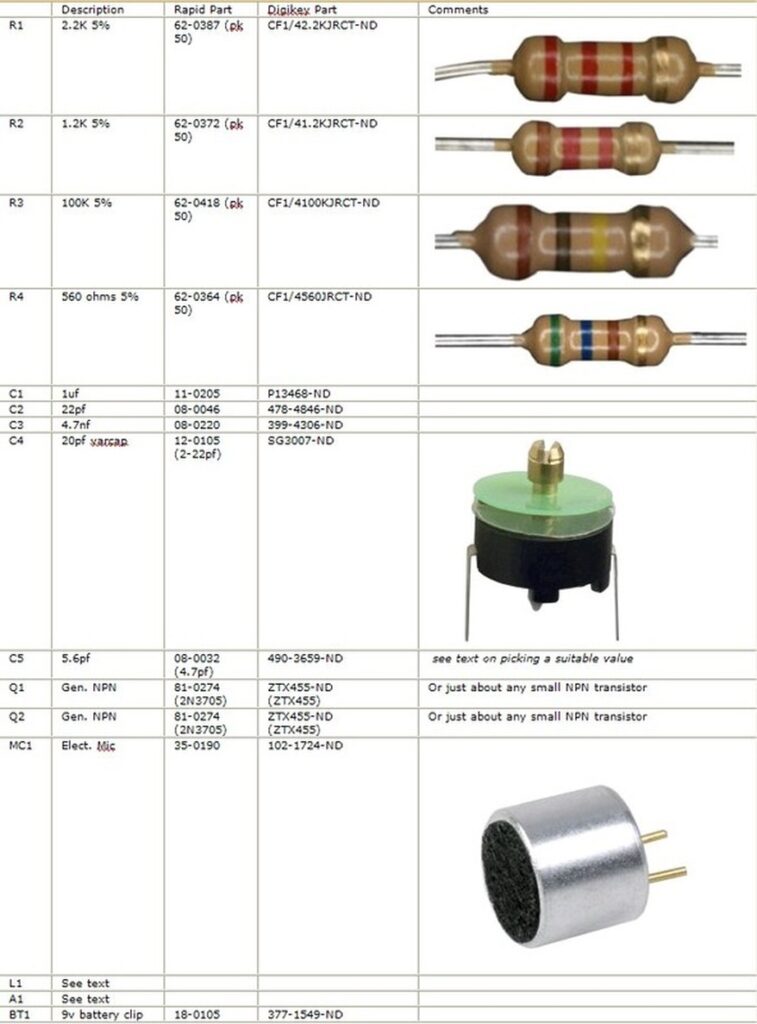
Below is a parts list. I’ve included suitable part numbers from both Rapid Electronics in the UK, and Digikey to make part selection a little easier.
It’s a fact of life now, that most mail order suppliers don’t want to sell you one resistor and so you may end up having to purchase in packs of the same value. If electronics is something your interested in perusing as a hobby, then this won’t be too much of a problem and it’s a great, cost affective way to start building a collection of components. The one thing to remember, is that except for Electrolytic capacitors and batteries, almost all other electronic components will stay useable almost indefinatly if they are stored in a dry, cool place. Electrolytic capacitors can tend to dry out over extended periods of times, even when they are not in use but they should still be completely serviceable even after several years in the bottom of your junk box.
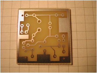
This project was designed to be mounted on a PCB, however you don’t have to. You could construct the project on Vero board (strip board) or any other 0.1” pitch style of project board. If you just want to experiment with this circuit, you don’t even need a board; you can just solder the component s together and let the completed project just rest on the work top. No matter which style you choose, try to keep all component leads nice and short.
You could also make the PCB much smaller than the one shown here which is approx. 3 cm square. This is a good size to keep the unit small but nicer to work on for beginners. If you wanted to make one really small, you could use all SMT parts.
Selecting the operating frequency range
The value of capacitor C5 controls the transmission frequency range.
In the UK, domestic FM radio receivers cover from around 88 – 108MHz.
The following table shows an approximate frequency range that can be expected for different values of C5.
These are only approximate as frequency is determined by the L1 and the specification of the transistors, but these ranges were observed in the prototype unit. Also note that the closer the coil windings are, the lower the frequency will be. Just slightly compressing the coil dropped the transmission frequency by over 1 MHz.
C5 Value Lower Freq. Upper Freq.
5pf 130MHz 180MHz
10pf 115MHz 152MHz
22pf 106MHz 124MHz
47pf 89MHz 97MHz
100pf 73MHz 75MHz
Again this is just a rough guide. Different makes of capacitors will give different frequencies.
I personally picked a frequency that was outside of domestic FM receives so that I wouldn’t bother anybody; and nobody else can “tune-in” by accident. However, if you don’t have a communications receiver then you will have to pick a frequency range that you can receive with your FM radio equipment.
Winding the coil
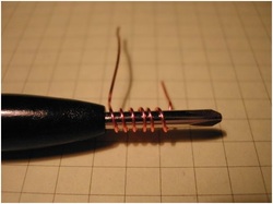
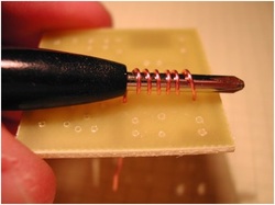
Figure 4 – Winding the coil
The first think to do is wind and mount the coil. The coil is simply a length of 0.6mm / 22swg copper wire wound into a coil. Take a 10cm length of bare copper wire and wind it around a suitable former; the blade of a jewellers screwdriver or knitting needle is ideal.
You will need between 4 to 6 turns and you may have to experiment here. 6 turns gave my prototype a transmission frequency of around 120MHz. A coil with fewer turns should reduce the frequency.
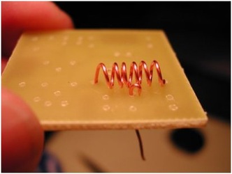
Mounting the coil on the board
Once the coil has been wound, leave it on the winding former for now so that it doesn’t get deformed whilst your mounting it. Pop each end of the coil into the correct PCB hole stretching the coil as needed so that its windings are evenly spaced. Turn over the PCB and solder in both ends of the coil.
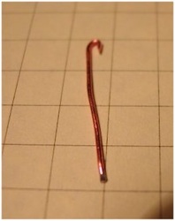
The above three images show how the coil centre-tap wire is made and then fixed to the coil.
Solder the centre-tap wire to the approximate centre position of the coil. When it’s secure, turn over the PCB and solder the wire to the track and trim off the excess wire.
Solder the remaining components
Next mount the remaining components except the transistors, in any order that you feel most comfortable with.
Lastly, you need to mount the transistors Q1 & Q2, and you need to be VERY carful that you insert them the correct way. Depending on which transistors you use, you may have to bend some of the legs around each other. If you need to do this, make sure that they don’t touch each other.
Now solder in the wires from the 9 volt battery clip making sure you get the positive and negative the correct way around.
Connecting the microphone
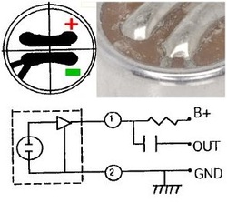
When it comes time to solder on the microphone you need to be carful. On the base of the microphone there will be two solder pads. If you look closely, one of the pads should be connected to the case; this is the Negative.
If you connect the mic the wrong way around it won’t work and you will probably damage it.
Notice above C1 in figure 6, there is a small link wire – “LNK”.
This allows power to be applied to the microphone via R1. If you decide to not use this type of mic or to connect the transmitter to another audio source, you should remove this link.
The aerial
You don’t need anything clever in the way of aerials for this transmitter. The longer the aerial wire is, the further the transmission range will be but for testing, just connect a 25cm length.
Make sure that the other end of the aerial doesn’t come into contact with anything; that includes any part of the circuit or anything that may be earthed.
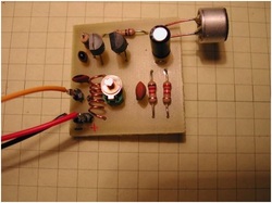
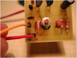
When you’re done, you should end up with something that looks like the picture on the left.
First tests
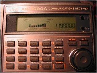
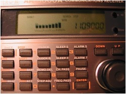
Figure 9 – FM receiver showing 119.9 MHz
Ok, now for the tricky bit. Assuming you’ve connected everything together correctly, then depending on the transistors used, tolerance of the components, characteristics of your coil and position of the trimmer capacitor, when you connect the battery you will be transmitting audio somewhere on the FM band, probably between 80MHz and 150MHz.
Place your FM transmitter near an FM radio and SLOWLY start to tune from one end of the band to the other. As you tune the radio with one hand, keep gently tapping the microphone on the transmitter with the other hand. At some point you should hopefully start to hear the tapping. When tuning you need to experiment to find the exact frequency. When you find the frequency, make a note of it and keep going a bit further. Sometimes you can find a stronger signal a little further down the dial.
Those using a communications receiver or scanner should select WFM or Wide FM if available.
Changing the TX frequency
With the component values specified, both my trial units popped up at around the same frequency.
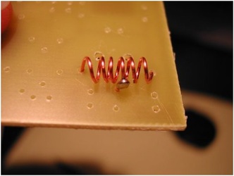
I then “crushed” the coil slightly; almost certainly one or more of the turns are now shorting together (see fig.10) and this immediately lowered the transmission frequency.
When tuning the transmitter don’t touch any part of the circuit as you will cause the output frequency to drift around.
Now the microphone used has a built in audio amplifier (see Figure 7) and I kid you not, it can hear an ant blowing its nose at 50 meters. If you just speak softly close up into the microphone it will probably sound distorted because you will overload the input.
These are ideal room bugs…. ermmmm… apparently…. not that I’ve ever tried that of course.
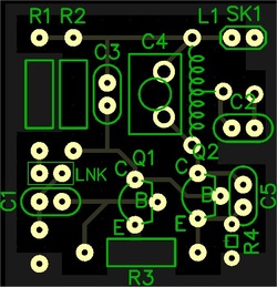
The PCB was designed using DipTrace PCB software and there is a free version of this product available for download that can be used to modify or print the foil. You will find the original PCB foil for download at the end of this article.
One question this is often asked is “what’s the transmission range?”.
Well it depends on many external factors including, number and density of obstacles between the transmitter and receiver, sensitivity of the receiver, the quantity and strength of other transmissions on or around the chosen wavelength that can overload the receiver, and the size of transmitting and receiving aerials. As a rough guide, assuming that a clear part of the frequency spectrum can be located and a nice long aerial is connected to the receiver, I’ve had around 250 meters in the city or built up area with a one Meter wire aerial on the transmitter, but a fair bit more distance out in the open or it it’s used up high.
Reducing the value of R4 will increase the drive to Q2 thus increasing the transmitter power output. However, if you reduce R4 too much you will shorten the life of the battery and will eventually destroy transistor Q2.
Leave a Reply
You must be logged in to post a comment.