
So I’ve been working tirelessly, day and night (well, I’ve given it a few hours anyway) to move the project forward.
Below is the latest version of my documentation. I’m having to document decisions and ideas because I just forget them, so my terrible memory is your good fortune. This isn’t the best way of doing things, and I’m sure there are lots of mistakes I’m making or about to make, but I don’t really care. The fun is in the building and the discovery.
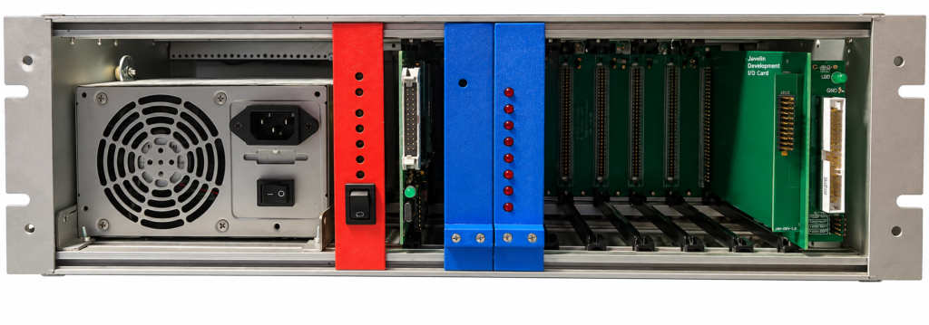
9 Slot, 19″ System Rack
The above image is the 19″ rack I will be using to house the Javelin computer. It’s the chassis that currently houses my 6502-development system. On the left is a regular PC PSU that is capable of supplying more than enough current for any sensible application. The red board is the power status and management controller (some LEDs that indicate all the voltage rails are ok and an on/off switch) and then 9 parallel connected expansion slots form a passive backplane. The above rack currently has my 6502 board, address controller an LED output card and an expansion connector that allows me to plug in a breadboard for hardware development.
All these will be removed; except for the PSU and power status and management controller, and replaced with the Javelin boards.
The plan is to have up to 4 x Javelin CPUs, 2 memory boards with a total of 16M-words of RAM and ROM, a 4-port serial board and some type of mass storage device; probably something that can support a couple of SD cards.
Just a note on my component selection choices. Since I am now retired and I can’t just spend money on anything that looks shiny and new, I’m trying to design and build Javelin using parts that I’ve already got or, at a push, I have to buy but are cheap. I’m lucky in that I’ve spent years amassing a huge selection of parts for projects like this, so hopefully it won’t cost me too much money, other than the PCB costs and I’m trying to keep those to a minimum buy only using 2 layer boards. This proved a bit of a challenge for the CPU card but I got there in the end.
I’ve ordered my first set of PCB’s from JLCPCB and they should be arriving in a few days, hopefully.
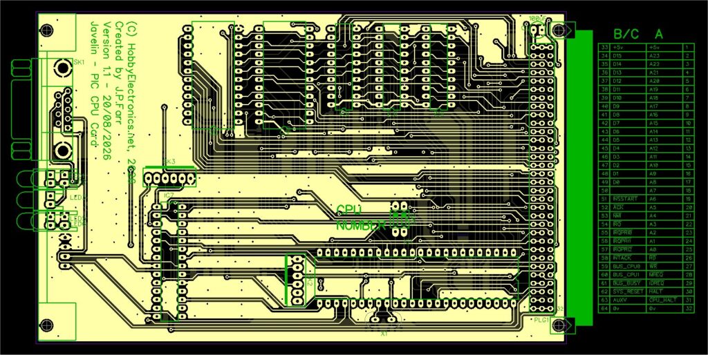
Javelin CPU Card
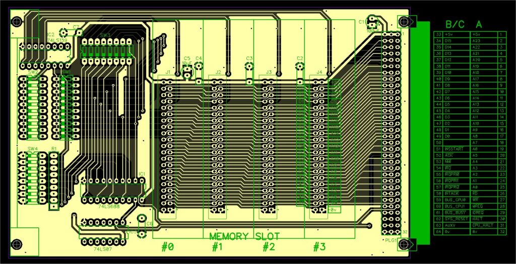
4 x Slot RAM/ROM Memory Card
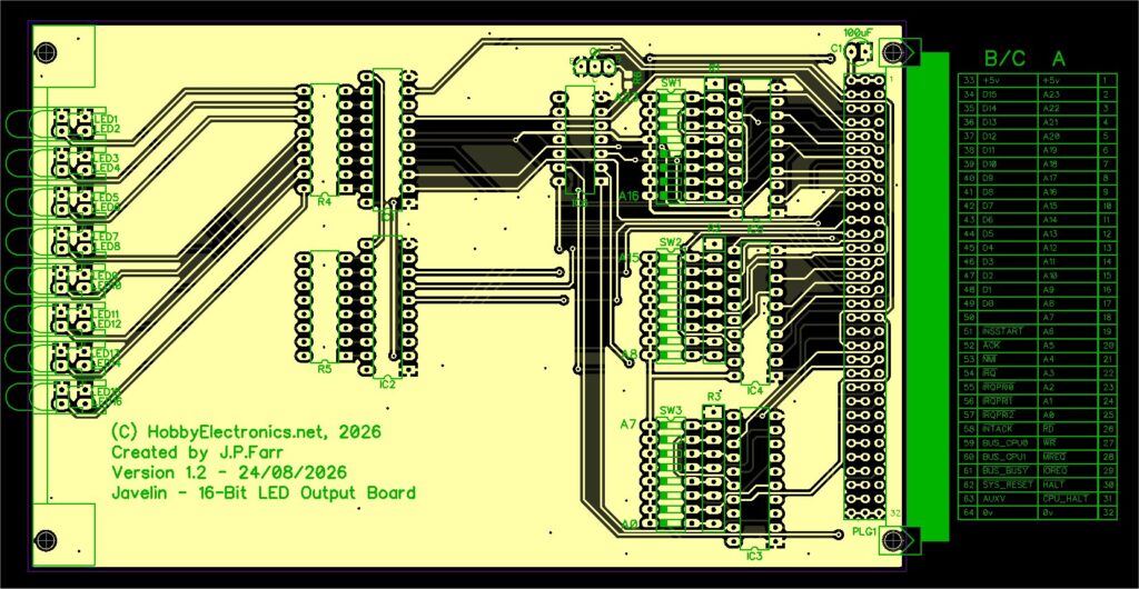
16-Bit LED Output Card
Once I’ve gotten some of the bugs out, I’ll make available the schematics and PCB files.
The CPU card will use a PIC18F57Q43 because it has a lot of I/O pins, a load of RAM and Flash memory space, is cheap, and I’ve got a small pile of them left over from another project. I’ve got them in square TQFP packages so I’ll have to mount the CPU on a 48 pin TQFP to DIL converter. I don’t think the fully loaded part is available in a DIL package which is a shame.
The memory card proved a challenge but I came up with a design that I’m happy with. Each memory card can accommodate 4 x Plug-in memory modules. The memory modules can be any size from 8K upwards, and there are configuration DIP switches to select the size of the modules. The only restriction is that all modules on a memory board must be the same size.
The LED I/O board is one of those boards that I build for every computer system I create. They are really simple to address and communicate with, and you can use them for outputting debug or status information.
Whilst I wait for the PCB’s to arrive I’ve been working on the first pass of the CPU instruction set. (See the attached PDF below). It’s a challenge since I’ve never designed a CPU instruction set before, so I took some of the ideas from the Nixdorf 8870 mini-computers I worked on years ago (1559 CPU).
I’m quite happy with the progress so far, and am eager to get a CPU board built and debugged.
Leave a Reply
You must be logged in to post a comment.