
There wasn’t going to be a part 3, but now I’ve completed the refurbishment of the 6 kits that I’ve recently obtained, I thought it worth a summary.
The kits all came from different sources and are of different ages and conditions. The one thing that was constant throughout all the kits however was corrosion. These kits are around 35 to 50 years old, but all seem to have suffered from various degrees of corrosion to the component leads, and in many cases the leads had actually failed/broken.
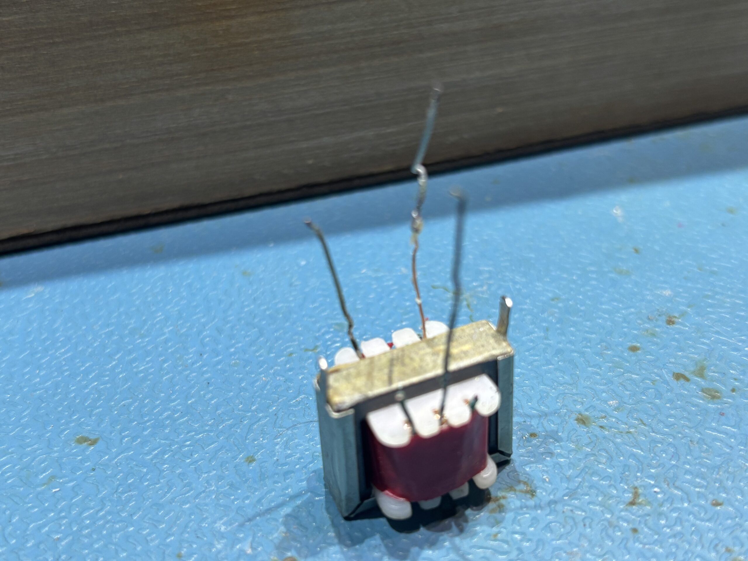
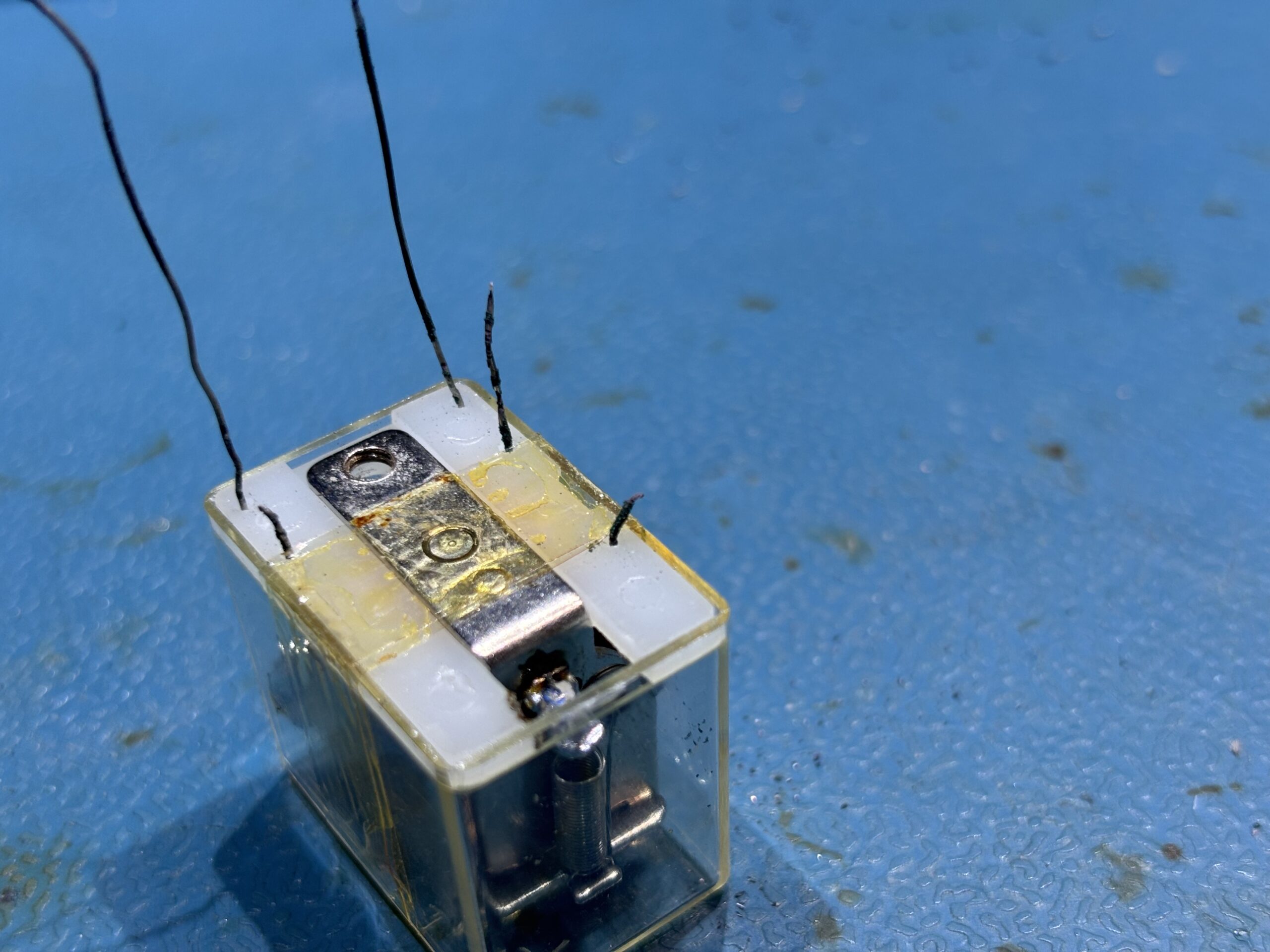
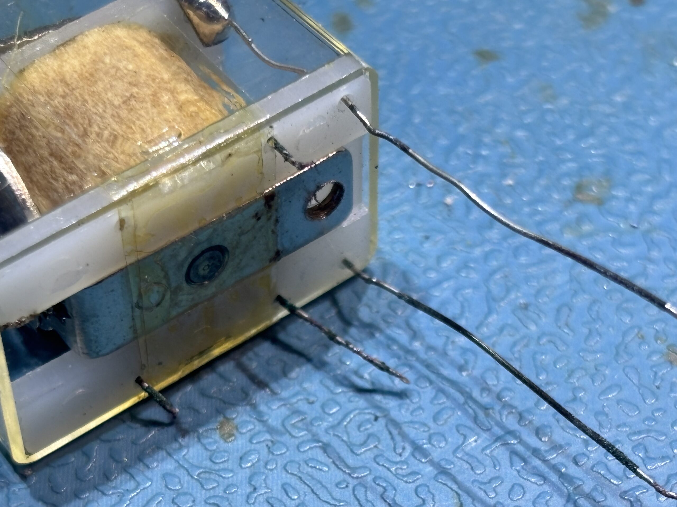
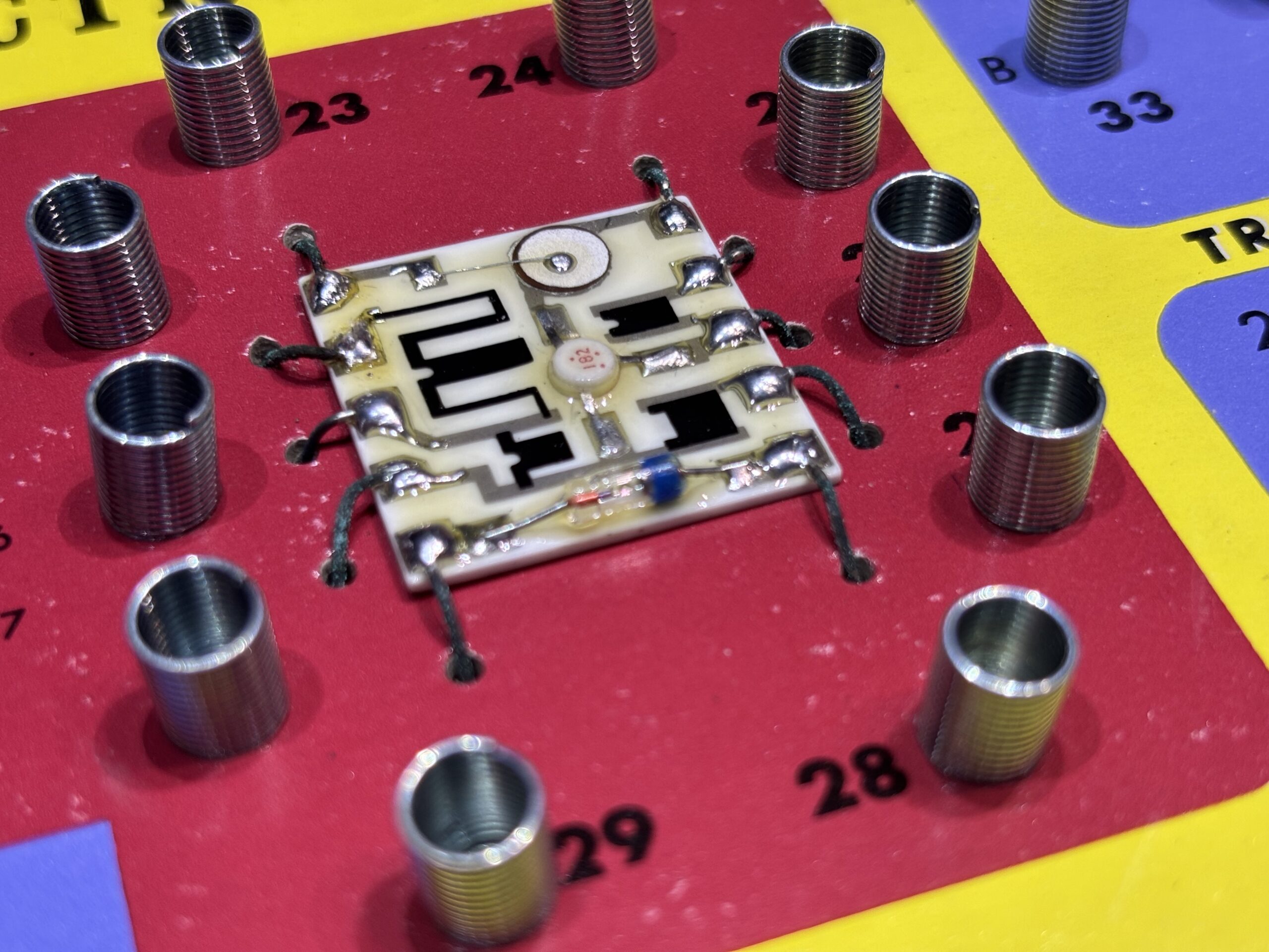
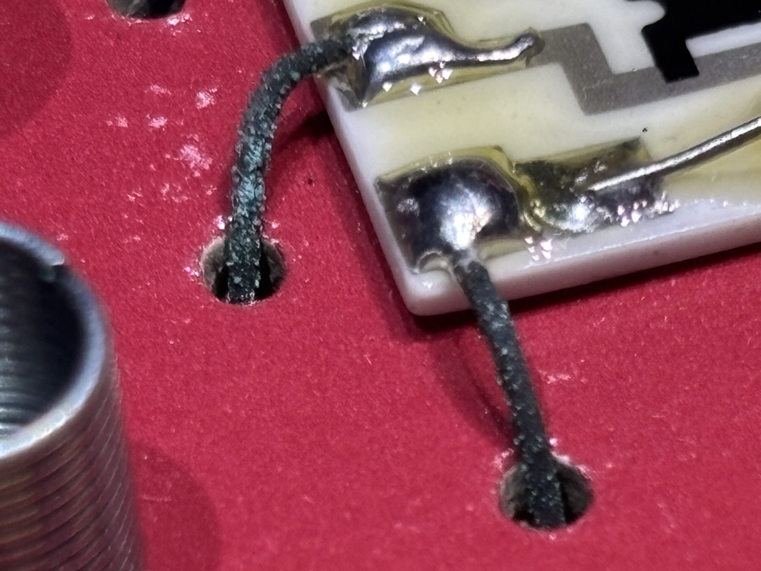
The above gallery shows some examples from the last kit I restored; the Science Fair 100 in 1 kit.
The transformer leads again were badly corroded as were the relay leads. The transformer was a write-off as when I tried to do my trick of cutting the red insulation tape and gently pulling on the tiny bit of wire remaining, it just snapped. You could see the corrosion had travelled up the wire into the transformer winding. The relay was tricky but repairable. The coil wires were gently pulled and gave me enough wire length to solder on fresh leads. The remaining 3 leads used for the relay contacts were easier to replace. The “IC UNIT” leads were very badly corroded; a couple had broken off on the underside. There is some conformal type coating over the IC unit but it didn’t present an issue and I just used a soldering iron to heat the joint. Just took a couple of seconds longer and gave a rather nasty plastic smell as it burnt off the coating.
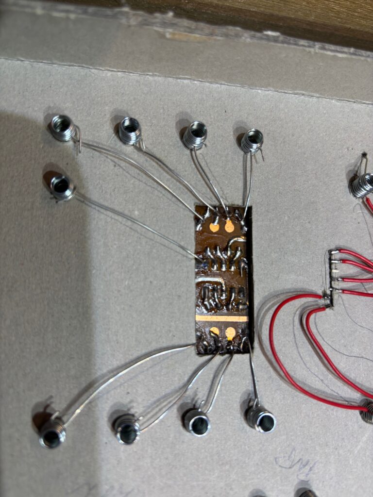
Some of the kits contain proper ICs or seven segment displays that have been soldered to a small carrier PCB. There are then wires from this PCB to the springs. On several occasions I’ve found that a gentil sideways tug on the wire at the PCB joint end with a pair of tweezers was all that was required to make the joint fail and the wire come away. I’ve made a habit of replacing these wires if they are at all corroded but in any case, always redoing the soldered joints.
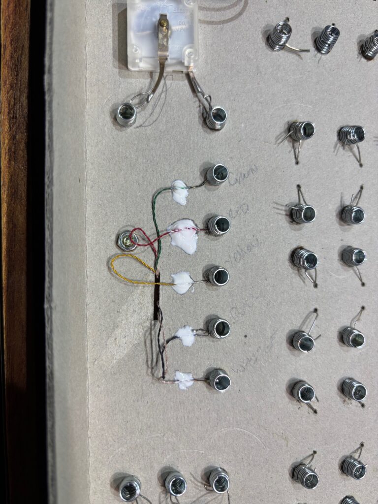
Many of the kits contain a ferrite rod aerial and you need to check very carefully the wires from the coils to the springs. They use very thin wire for the windings and it’s also not immune to corrosion. I’ve taken to tugging the wire at the spring end gently to make sure it’s solid, and then dropping on some glue spots to hold the wires in place. I wrote the colours on the cardboard when the wires started falling off on this kit.
I’ve also found several of the disc ceramic capacitors where the leads have failed. Everything looks ok from an initial inspection, but testing the capacitors shows an open circuit and when you remove the capacitor, one of the legs just drops off. Whilst on the subject of capacitors, some of them are wayyyyyy out of spec and I’ve started replacing the electrolytics just on principle. They are typically low voltage, low capacitance so cheap to replace.
Resistors and capacitors are easy enough to replace, most of the remaining components aren’t so simple.
Some of the kits use slide switches and a squirt of switch cleaner/De-oxit and wiggling the switch for a few seconds can being that back to life or improve the contact resistance.
Some of the older kits have germanium transistors that are rather expensive to replace and I have to be honest here. If they tested good whilst still in place, I’ve left them even though I can see the leads are corroded. I plan to build some of the circuits in each manual and then experiment with replacing the supplied transistor with a silicon one to see how things go. I can always slip in an addendum sheet into the manual if needed. Original replacements can easily cost £5 to £10 each, and that’s more than I usually paid for the kit.
The germanium diodes in some kits are still available as NOS (New Old Stock) but can be expensive. I’ve mentioned this before, but be vary wary of Ebay sellers advertising germanium diodes cheap. If the diodes have an orange/bronze coloured body and a black band, then they are probably Schottky diodes. Now these may actually work, but they certainly aren’t germanium ones. I intend to try some experiments to see if this Schottky diodes are a suitable replacement in these kits.
The 100 in 1 kit as a component that is marked “RFC”. It’s actually a 2mH inductor with a resistance of around 6 ohms, wound on a ferrite bobbin. You should be able to find a suitable replacement easy enough. Look for a 2.2mH one.
The red transformers are Eagle LT700, and the yellow ones are Eagle LT44’s. Both are available if you hunt around but expect to pay around £5 each.
Most of the kits have jumper wires missing and these need to be replaced and I’ve found that many of the instruction booklets have a list at the back that details how many of each colour/length is supplied in the kit which makes things a lot easier. The 100-in-1 kit is an exception and doesn’t, so I had to go through all the experiments and work out the maximum number of each type that could be used.
You can find suitable wire on Amazon here: 26 AWG PVC Electrical Wire -SCHDRA 0.13mm²Electrical Wire,Tinned Copper Wires(6 Colors 6 Meters/20ft Each Color)(OD: 1.3 mm),Stranded Wire-for Electronics, DIY Projects, Automotive Wiring : Amazon.co.uk: DIY & Tools
Make sure you get the 26 AWG type.
To test the ICs that some kits have, the easiest way was to flip though the manual and find an experiment that uses as many of the gates in an IC as possible and build it. It was also kind-a fun to do.
The one thing I’ve not had to replace are any of the red bulbs. That will be interesting trying to either find or make one when the time comes.
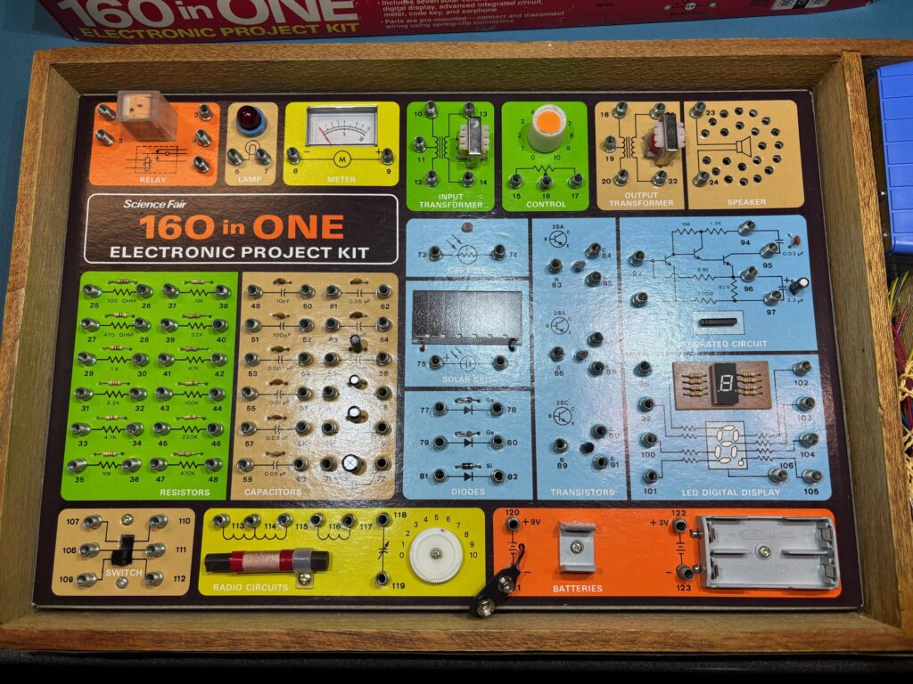
The above 160 in 1 kit is the one that took the longest to refurbish. Every component and had to be removed. All the resistors and capacitors and a diode had to be replaced. I also replaced the yellow NT44 transformer and spent an age repairing the red Eagle LT700 one. Likewise the relay needed to be disassembled and rebuilt.
The other thing I’ve done is pop a large packet of silica gel (moisture absorber) into the box. These boxes aren’t exactly air tight, so not sure if it will help or make things worse, but I thought I’d give it a try. Actually, I’ve got some large vacuum sealable plastic bags. I may pop them into those.
Jumper wire requirements per kit
| Kit | White 7.5cm | Red 15cm | Blue 25cm | Yellow 35cm | Black 38cm | Green 3meters |
| 150 in 1 | 11 | 14 | 8 | 7 | 2 | 1 |
| 160 in 1 | 11 | 14 | 7 | 7 | 2 | 2 |
| 200 in 1 | 39 | 20 | 15 | 4 | 0 | 1 |
What has surprised me is that it’s clear some of the kits have been very well used. There are scribbles (most seem like sensible observations and comments) all over some of the manuals, the wires are clearly well used and somebody has obviously had their fun with many hours spent with their kit. But other than components being damaged through corrosion, I’ve found only a couple of actually faulty components (and this could be environmental rather than carelessness). In so many ways these kits have stood up to the rigours of children’s fingers, their warped imagination and time very well.
Leave a Reply
You must be logged in to post a comment.