
In the first part of this thrilling saga, I dropped a cliff-hanger and warned that whilst these kits often look in pretty good condition, trouble lies underneath.. underneath the cardboard panel as it happens.
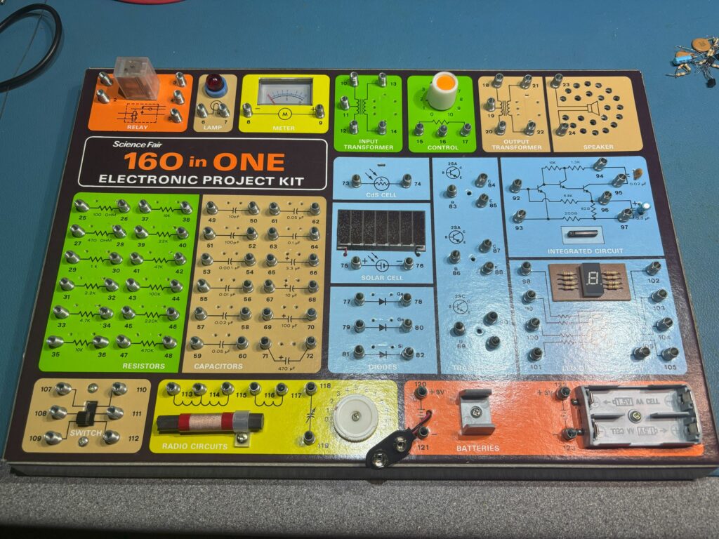
Today, I have a 160 in 1 kit from Science Fair on the bench that I’m going to restore. Due to a technical error (I actually forgot) I don’t have a before picture, but this kit appeared to be in excellent condition until I started testing things.
If you do get one of these kits, to avoid the crushing disappointment when a circuit doesn’t work, I would suggest you test every component in the kit first. Straight off, there was a problem with one of the transistors, and there were open circuits on both of the transformers. One of the segments on the LED display wouldn’t light and the bulb didn’t work. The bulb was an easy fix, it was just lose in the socket. Unfortunately, the rest of the problems meant accessing the underside of the panel. After carefully running a knife between the cardboard panel edge and the wooden tray base a few times, I managed to break the glue fixings and the panel just lifted out.
You can’t really see in the above picture, but I’ve already removed most of the components, and before you ask, yes, there was a very good reason for having to do this.
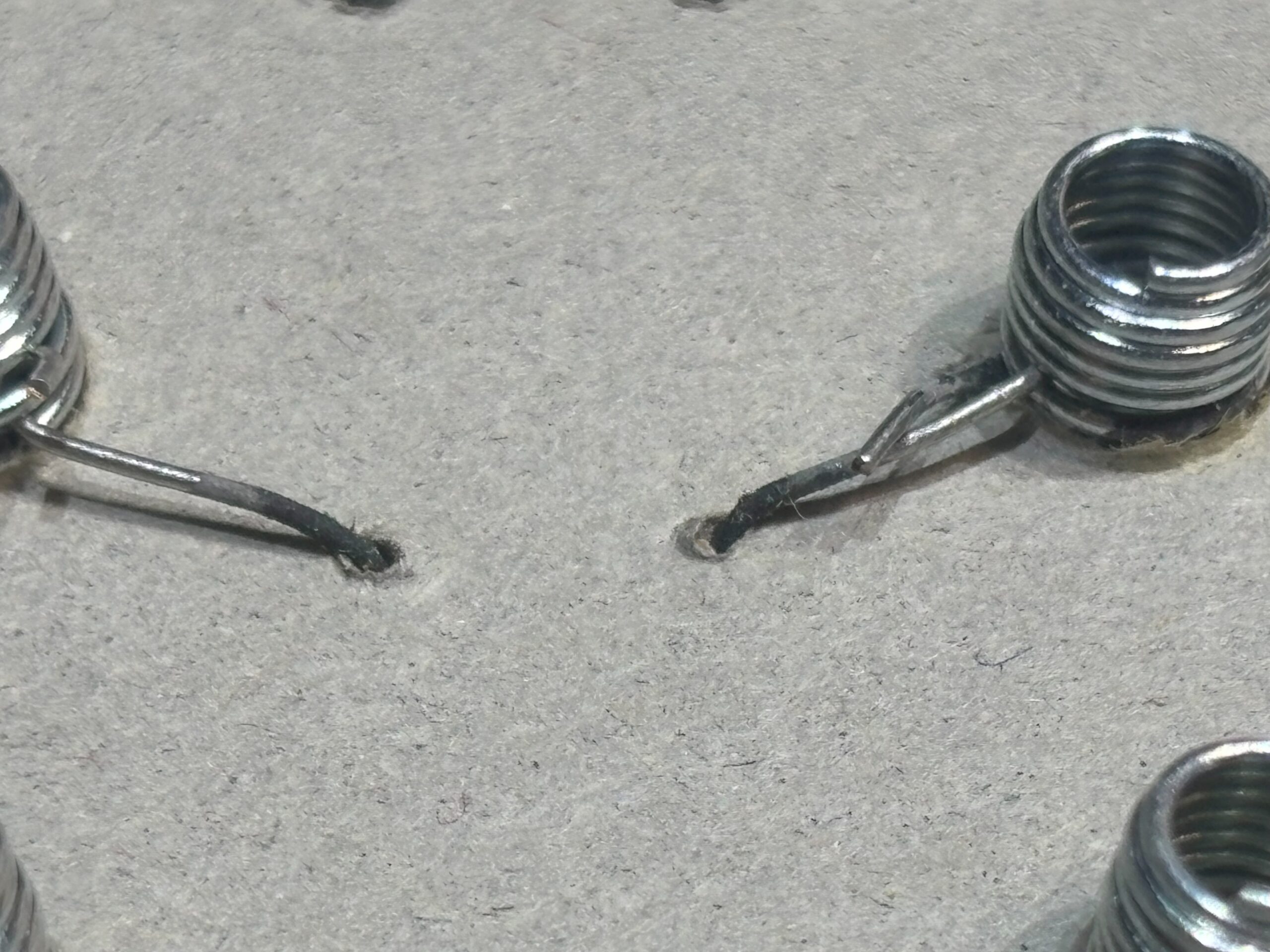
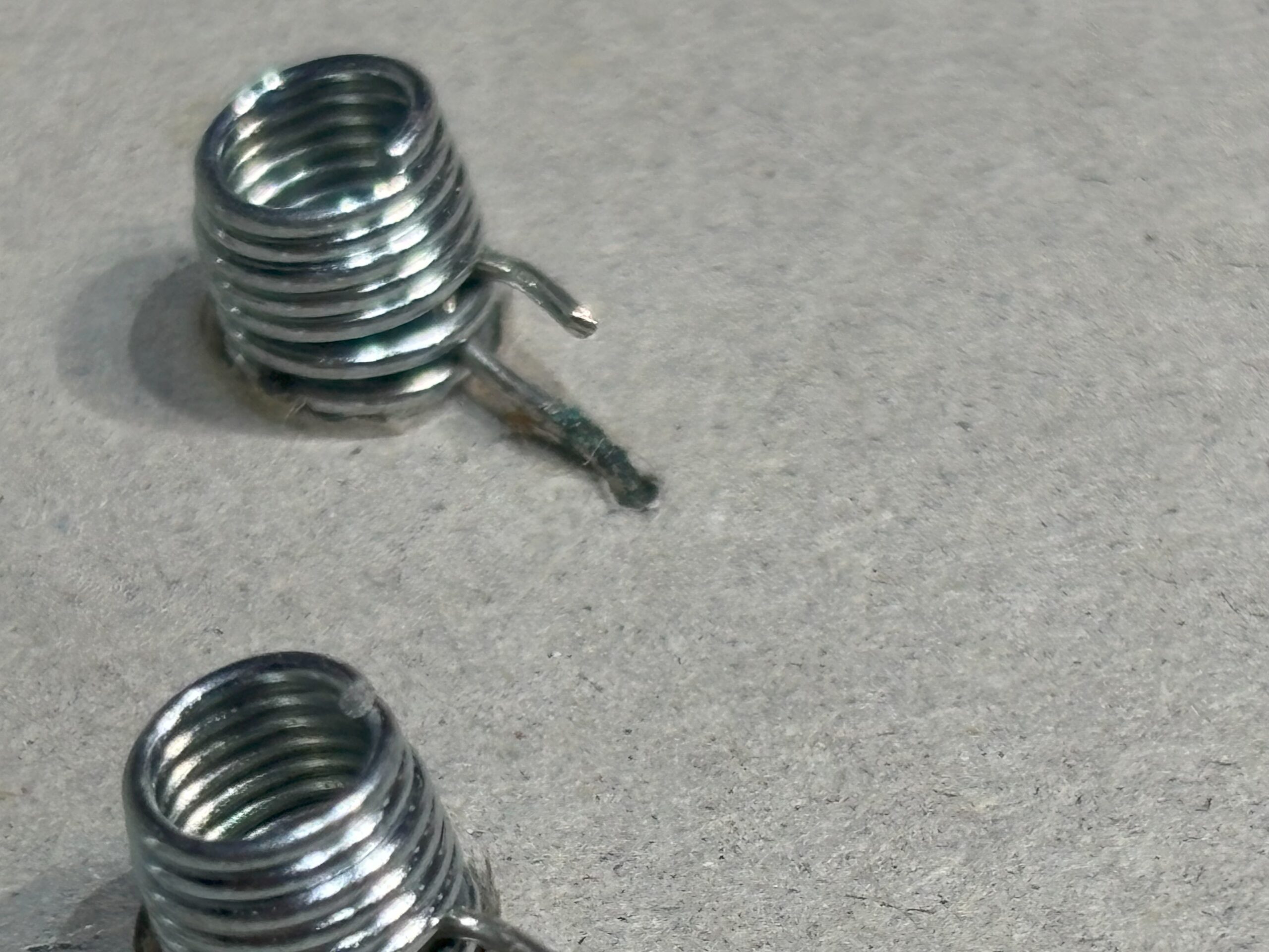
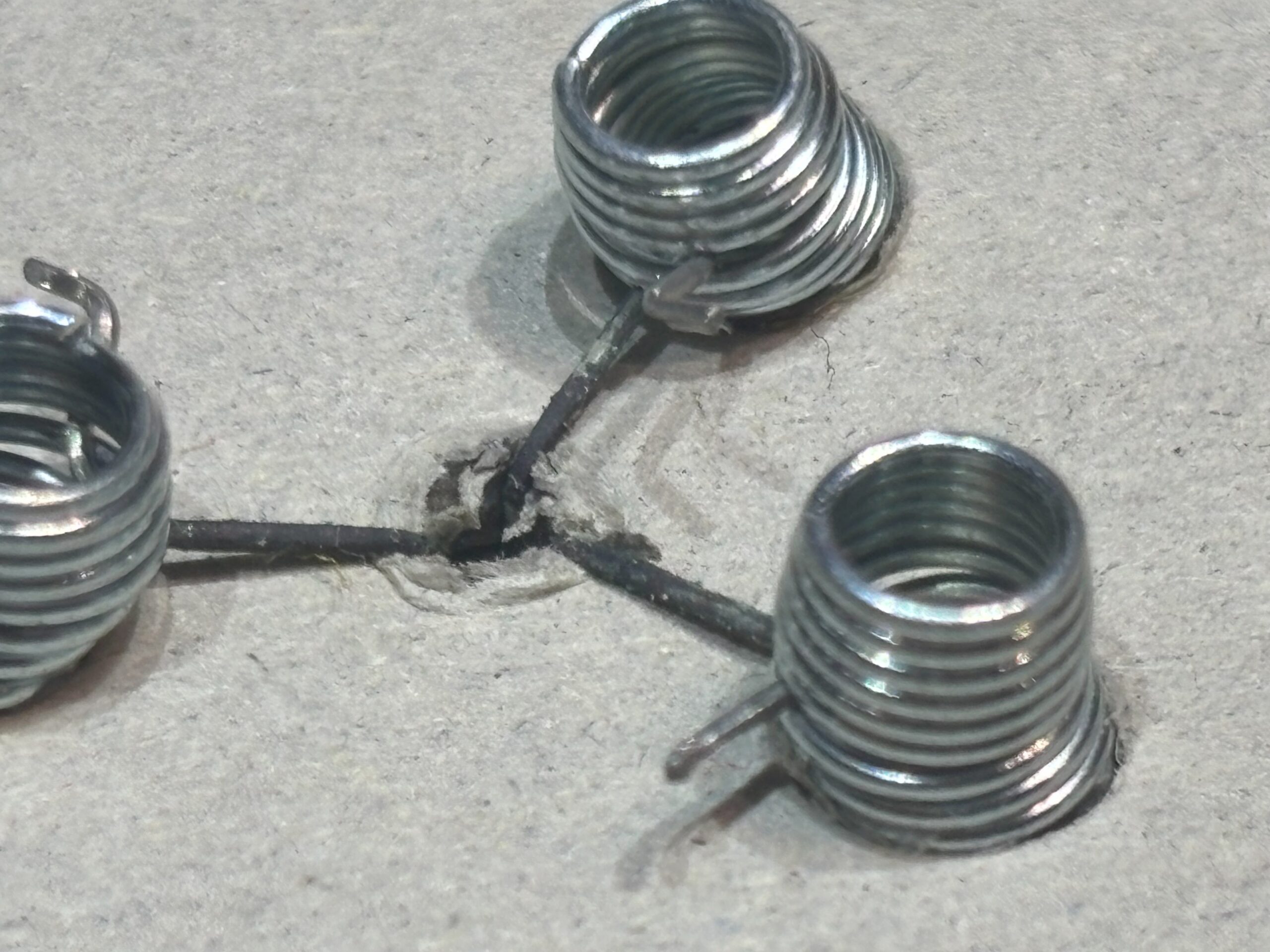
The above images show the corrosion that has occurred on the underside. I think this was caused by a combination of moisture being retained by the cardboard panel, and some weird galvanic reaction between the metal of the springs and the component leads and wire. Whatever the reason, it’s significantly weakened many of the connections and in some places completely eaten through the leads and wires.
The corrosion seems to start where the component lead passes through the cardboard, and this is typically right up against the body of the component. The corrosion will pass down the lead but also will eat away at the metal as it enters the component body causing the seal between lead and component body to fail. The component will fail at some point, even if it’s not already. The bottom line is this all needs to be cleaned up and affected components replaced.
Step 1, remove all the affected components. In the case of this kit, pretty much all of them.
Step 2, have a little cry when I see what the corrosion has done to the transformers.
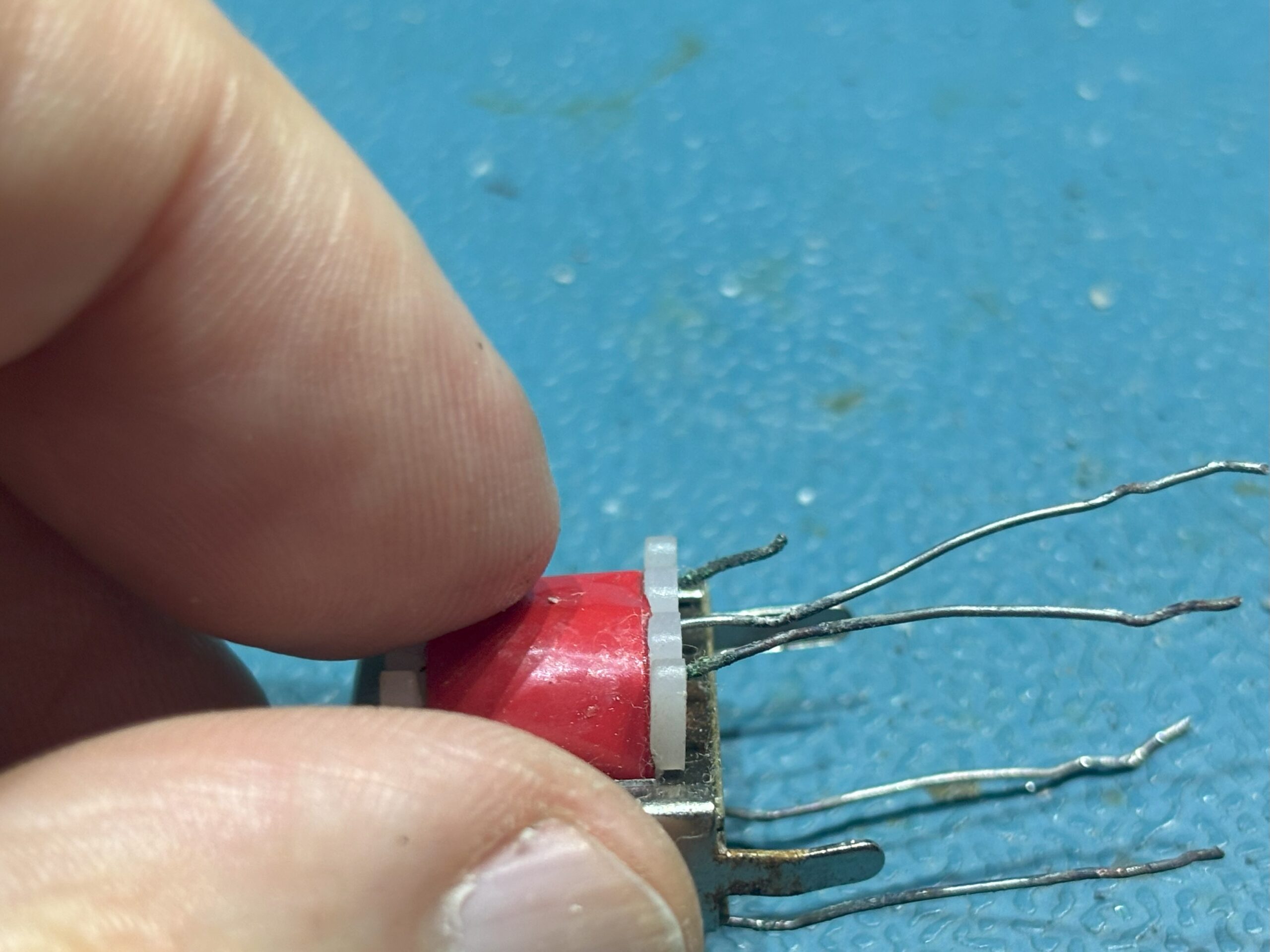
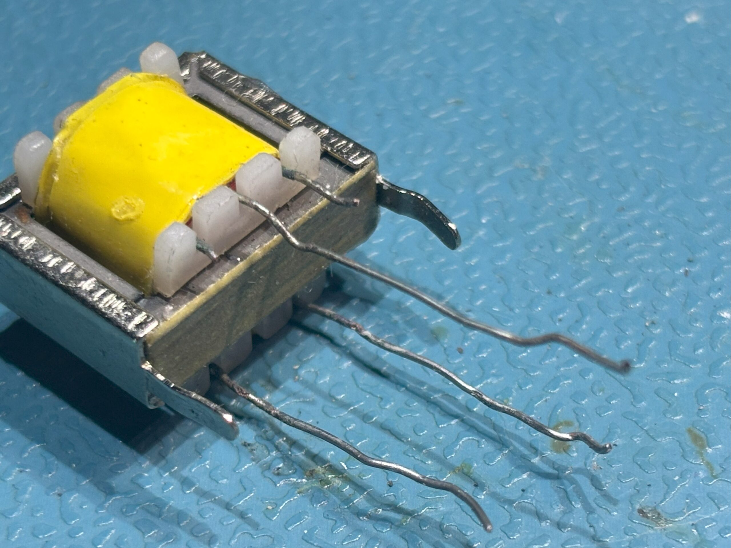
You can see the transformer leads are very corroded. Some had broken off, some broke during the removal process and others would break during cleaning. If you look closely at the lower two leads from the yellow transformer, you can see that the end of the leads close to the transformer body are almost eaten all the way though. They will break if you do anything with them.
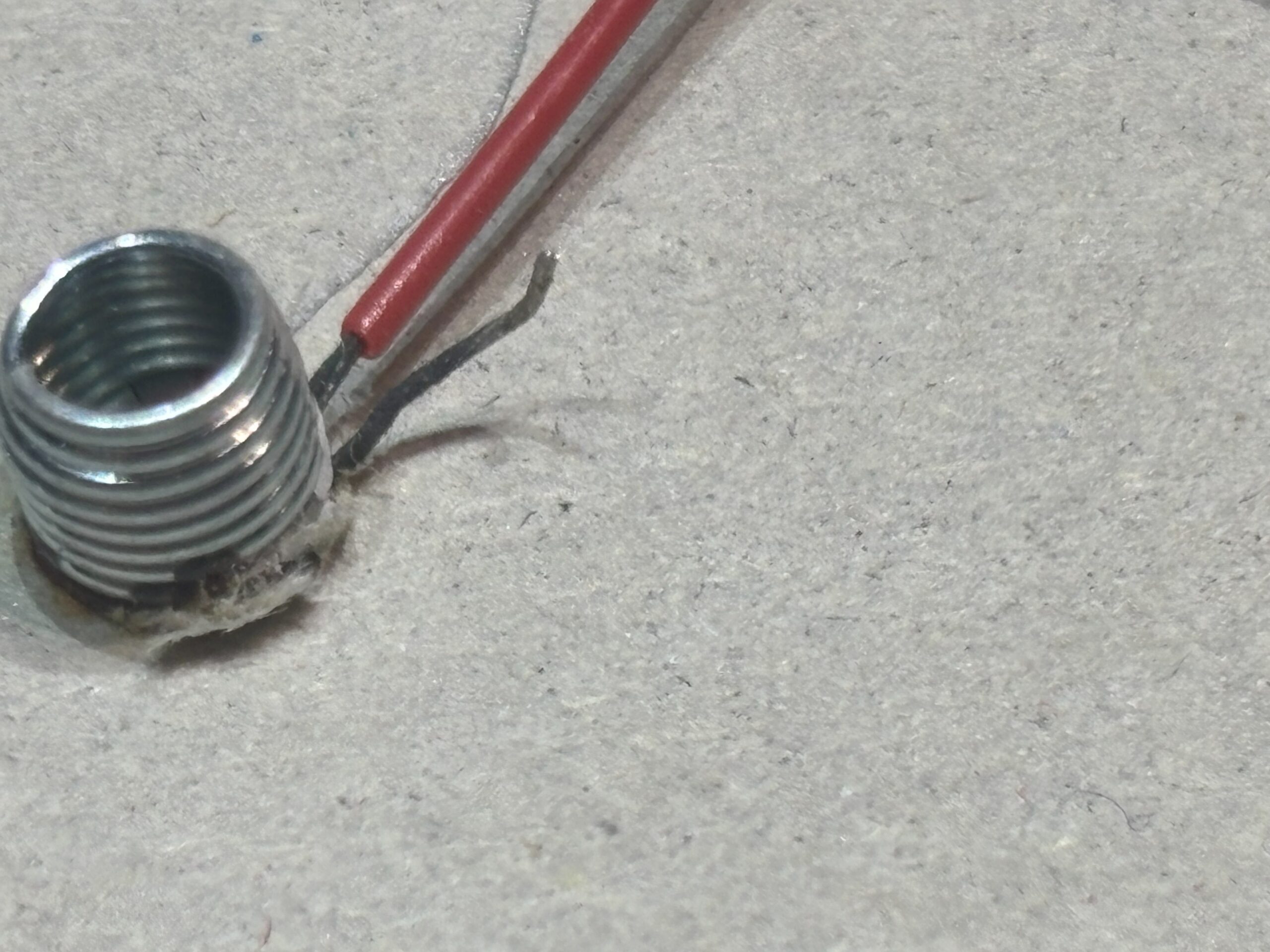
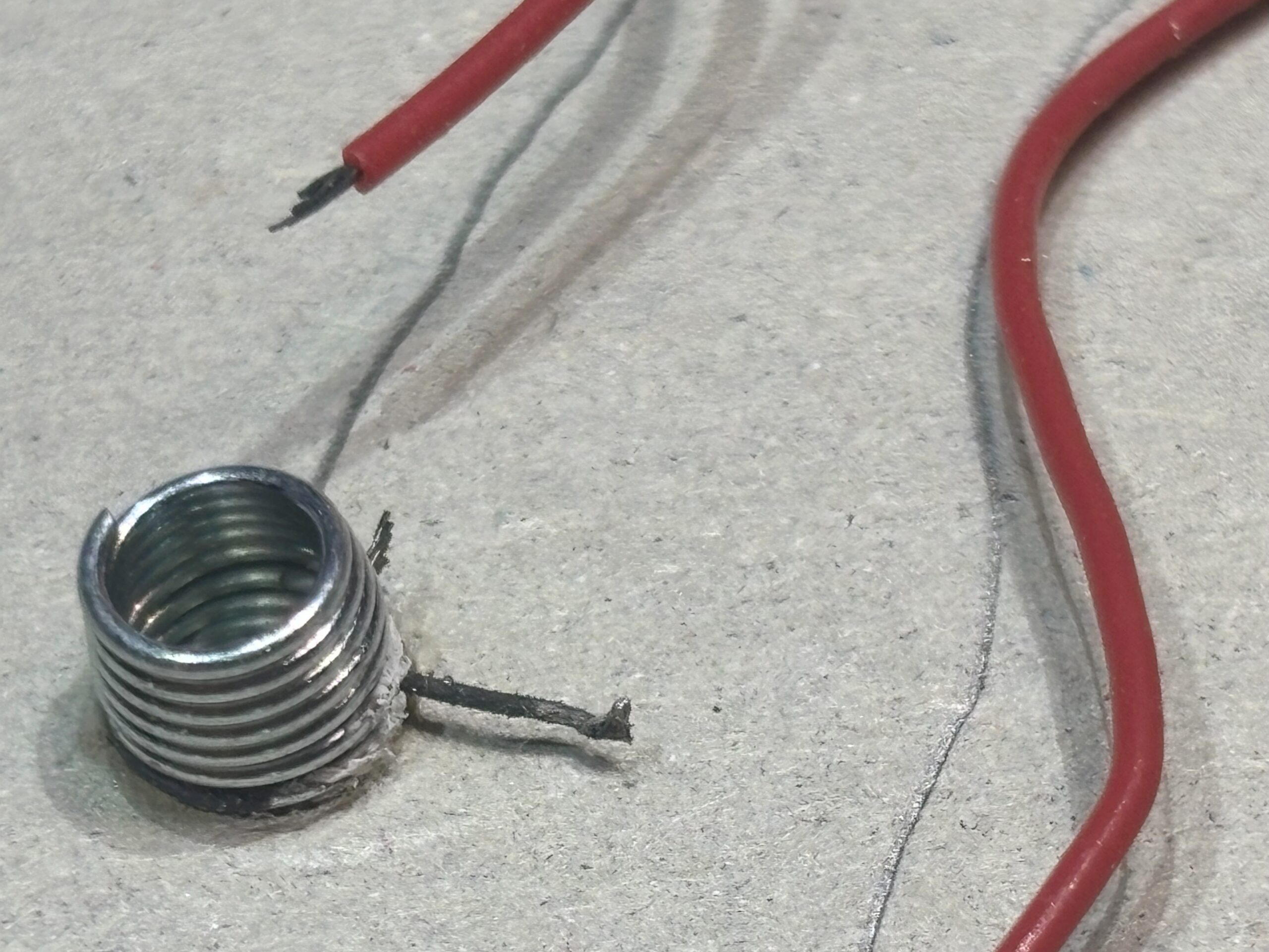
Step 3, there are metal wires that attach from the speaker, meter and several other components. These need to be replaced. You can see the corrosion on the metal wires and on the red stranded wire.
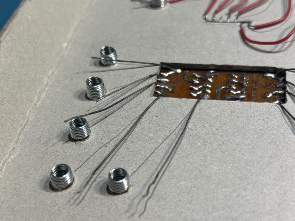
Step 4, replace the stranded flexible wires. This is an important one as you can’t always see just how bad the conductors have been corroded, but as can be seen in one of the above pictures, the corrosion is happy to eat anything metal. All the stranded interconnection wires need to be replaced. In my kit that are some wires from the bulb and these were really long. I trimmed them back to make sure that all the corrosion had been removed.
Now, I elected not to do anything with the springs. This may, or may not end up being a bad idea, but I’ve found that after removing and re-inserting the springs they aren’t held as firmly by the cardboard making them easy to pull out by accident. It’s a risk I know, but I didn’t want to have to glue them in, so my options were a bit limited. If necessary, I do have a plan B. I could remove the springs, clean them up, re-insert them and then slip a piece of very stiff wire through the base of the spring, up close to the cardboard. This should help keep them in place, but it’s a horrible time-consuming job.
Most of the components are off-the-shelf and are usually fairly easy to get, with a couple of exceptions. The component values in these kit’s aren’t usually critical. You can bet the original components weren’t of the highest quality or tolerance, so it’ fair to assume the circuits are designed to operate with this factor in mind. Also, the circuits aren’t exactly high speed, high frequency, or high fidelity, so using components with values that are close to the originals should be fine.
There are some tricky items however, and I’ll try and list those here.
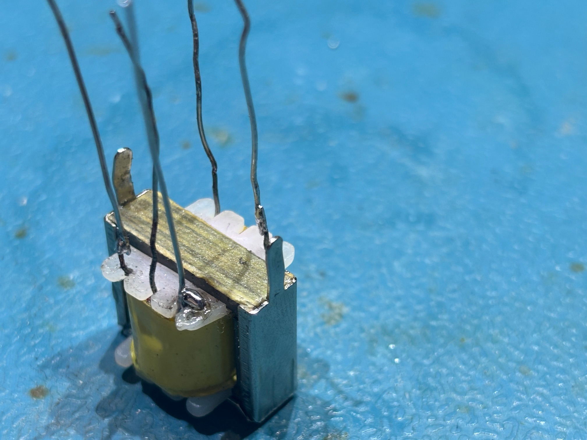
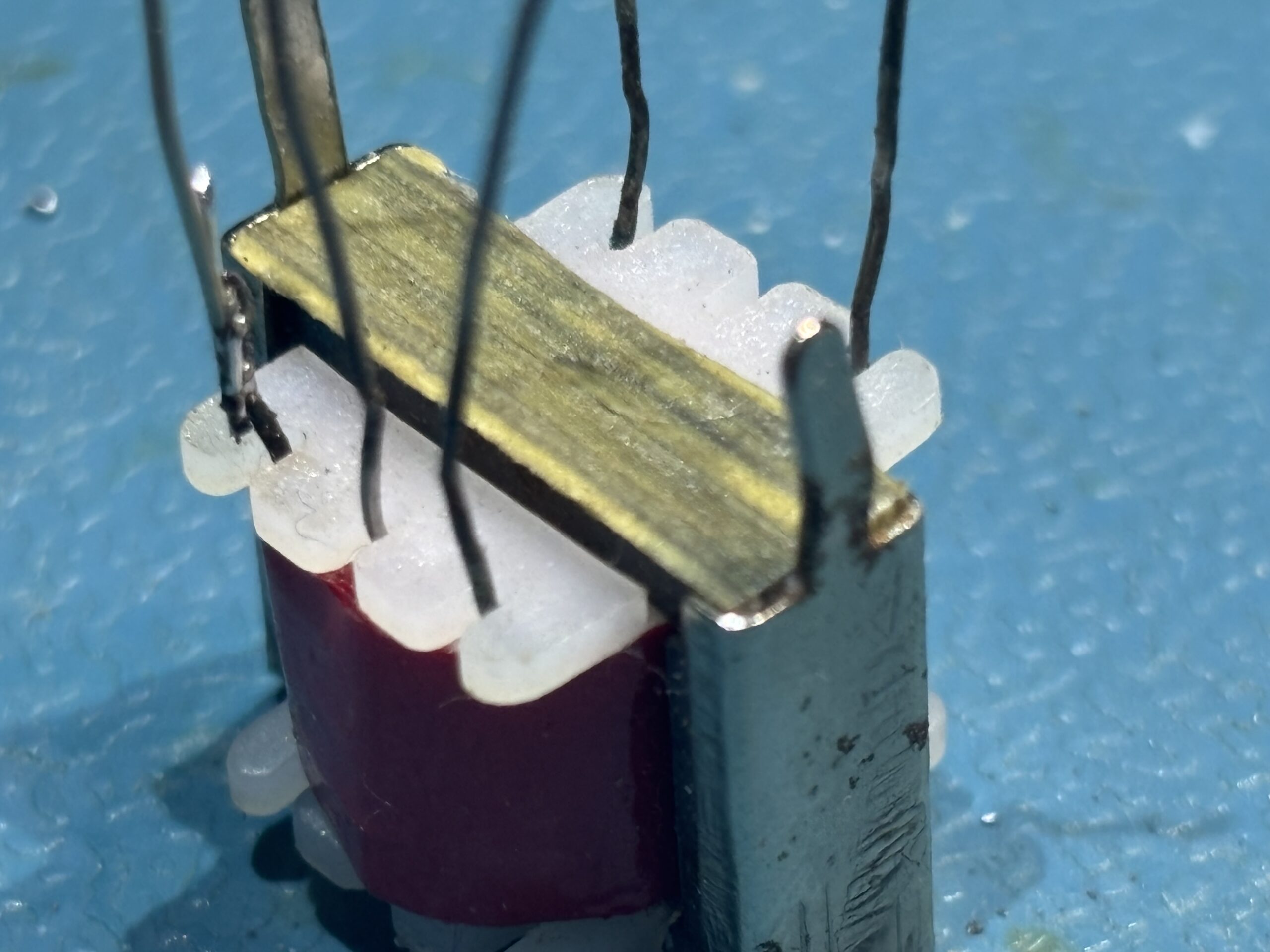
The transformers. The red one is an Eagle LT700, and the yellow one an Eagle LT44. In this kit, there are three transistors, 2 x PNP and 1 x NPN and they seemed to be just general purpose, so were replaced with BC547 (NPN) and BC557 (PNP). I would suggest you add a piece of sleeving to the centre lead on the transistors. How Tandy got away without loads of short circuits is beyond me.
There are sources of these transformers available, but in this case I managed to salvage both of the originals. I’m not sure how long the repairs will last as the lead corrosion was really bad and so close to the transformer body. But for now, they seem to work. The red transformer seemed particularly fragile, so after I eventually managed to soldered on extension wires, I covered the base in superglue to try and take the strain off the connections.
The 1/4 watt resistors and capacitors (minimum 16v rating) are all common enough.
This kit also contains 2 x Germanium diodes and 1 x silicon diode. The silicon diode can be replaced with a 1N4001 or 1N4007. Any general purpose rectifier diode rated for at least 1 amp should be fine.
The Germanium diodes are a bit harder, and you need to be VERY carful when sourcing replacements. Germanium diodes have a lower forward voltage drop than silicon ones, so some unscrupulous sellers try to pass off Schottky silicon diodes as a replacement. If the diode has an orange body with a black band, then be wary of what it really is. In reality they may work with just a reduction in sensitivity in some circuits. Suitable replacements would be 1N34A / 1N60P / OA91 / OA95 but they are getting harder to find and can be pricy these days. If they are really cheap, they probably aren’t what you think.
Some kits contain integrated circuits and for the most part, these will be standard parts. One known exception is the IC UNIT in the 100 in 1 kit. To be fair, you could make an equivalent of this on a small PCB if needed.
It’s too late for this kit as I’d already completed the refurbishment, but whilst I was writing this blog I had an idea. I’ve already stated that I slipped a piece of insulation sleeving on one of the transistor leads to help prevent shorts. If I encounter another kit that has obviously suffered from bad corrosion like this one, I will sleeve every component lead. That should stop any moisture hiding in the cardboard panel from attacking the component leads.
The last thing to do when restoring your kit is to inspect all the jumper wires. If they are in decent condition, you can snip the ends, re-strip and tin them and they will be as good as new.
If you need to replace them, then you want to find PVC insulated wire. It should have an outer diameter of around 1.2mm, contain 7 strands of 0.16mm wire, 26 AWG is a good match. This will give a good balance between flexibility and stiffness so they hold position when routed between connections and is the same specification as the original wires used. You can find this wire on Amazon in small reels of blue, white, red, black, yellow and green.
One final thing. Once you’ve assembled everything and are ready to go, take a couple of minutes to quickly check all the components to make sure you’ve not accidently left anything disconnected. Been there 🙁
Leave a Reply
You must be logged in to post a comment.